Building Wire
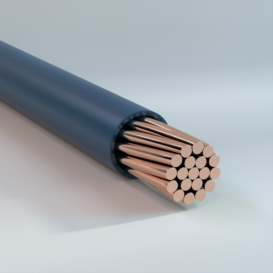
Copper Conductor
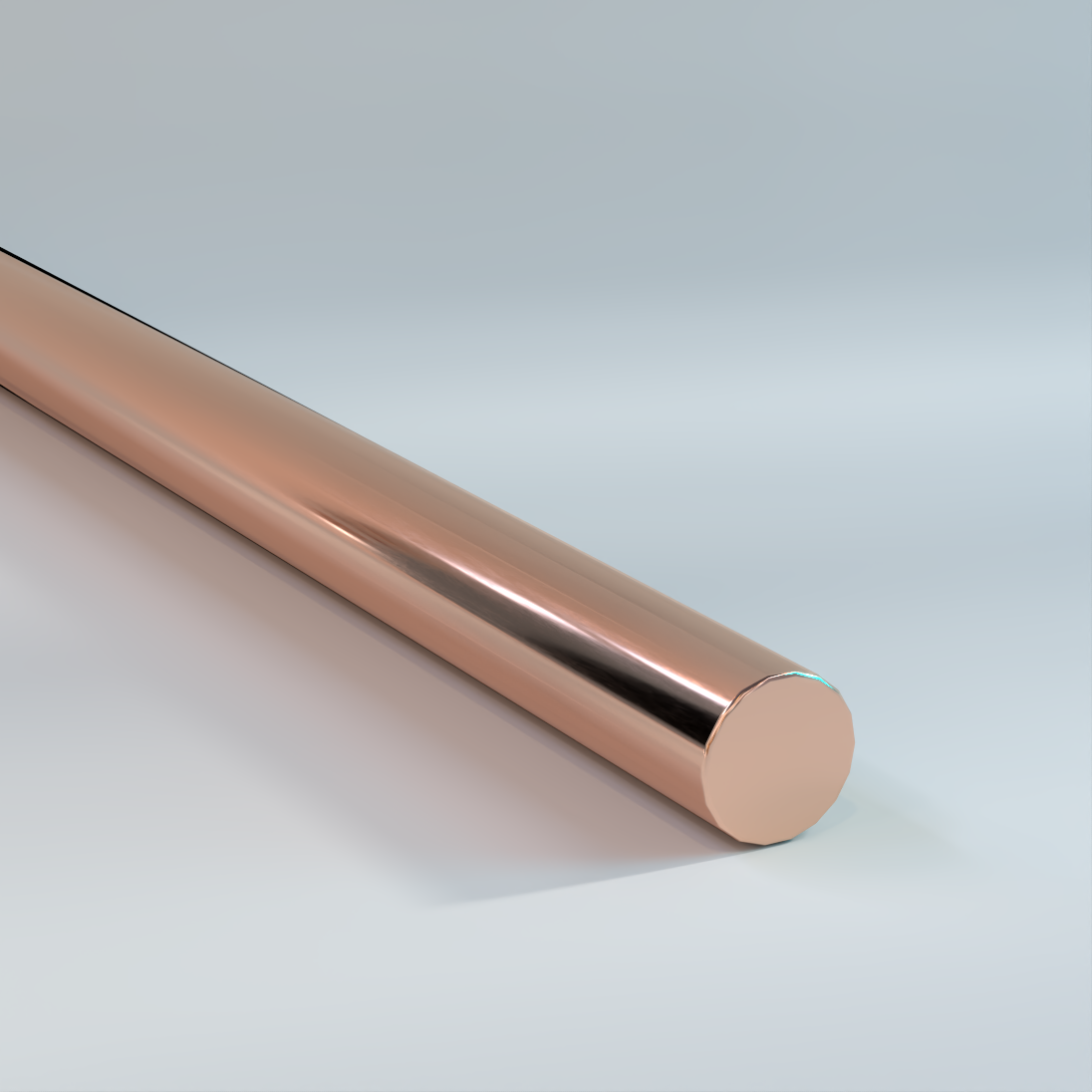
Bare Copper Conductor Solid
Hard, Medium-Hard, or Soft-Drawn
Used for grounding purposes in accordance with the National Electrical Code (NEC). Soft-drawn solid or stranded conductors are used for grounding connections in circuits, machinery, equipment, and counterpoise grounding systems. Hard-drawn conductors are suitable for overhead transmission and distribution lines and specified grounding applications. Also available tinned.
Physical Data
| Bare Copper Conductors Solid | |||||||||
|---|---|---|---|---|---|---|---|---|---|
| Breaking Strength | |||||||||
| Size | Area | Wire OD | Net Weight |
Hard Drawn Rated Strength |
dc Resistance @ 20 °C |
Medium-Hard Drawn Rated Strength |
dc Resistance @ 20 °C |
Soft Drawn (Annealed) Rated Strength |
dc Resistance @ 20 °C |
| AWG | cmil | in | lb/kft | lb | Ω/kft | lb | Ω/kft | lb | Ω/kft |
| 14 | 4110 | 0.0641 | 12 | 214 | 2.626 | 167 | 2.613 | 124 | 2.525 |
| 12 | 6530 | 0.0808 | 20 | 337 | 1.652 | 261 | 1.643 | 198 | 1.588 |
| 10 | 10380 | 0.1019 | 31 | 529 | 1.039 | 410 | 1.033 | 314 | 0.999 |
| 8 | 16510 | 0.1285 | 50 | 826 | 0.653 | 644 | 0.65 | 480 | 0.628 |
| 6 | 26240 | 0.162 | 79 | 1280 | 0.411 | 1010 | 0.409 | 763 | 0.395 |
| 4 | 41740 | 0.2043 | 126 | 1970 | 0.258 | 1584 | 0.257 | 1213 | 0.249 |
| 3 | 52620 | 0.2294 | 159 | 2439 | 0.205 | 1984 | 0.204 | 1530 | 0.197 |
| 2 | 66360 | 0.2576 | 201 | 3003 | 0.163 | 2450 | 0.162 | 1929 | 0.156 |
| The above data are approximate and subject to normal manufacturing tolerances. Where required, the compatibility with glands, connectors and accessories should be verified using actual dimensions of the product. Other sizes available upon request. | |||||||||
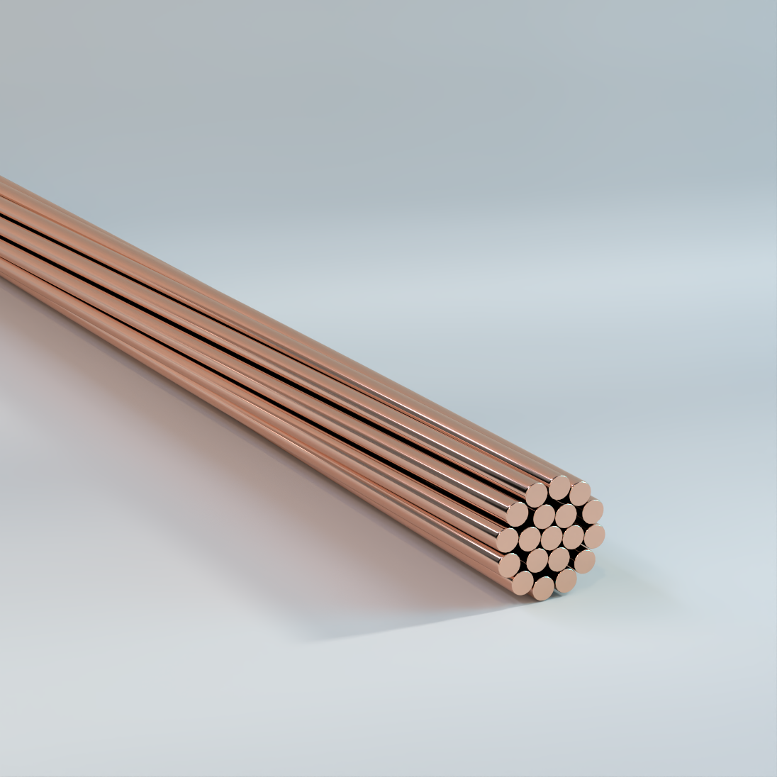
Bare Copper Conductor Stranded
Hard, Medium-Hard, or Soft-Drawn
Used for grounding purposes as specified in the National Electrical Code. Soft-drawn solid
or stranded conductors, for use as grounding connections in circuits, and grounding for
machinery or equipment. Hard-drawn conductors for overhead transmission and
distribution lines, as grounding connections in circuits, and grounding for machinery or
equipment. Also available tinned.
Physical Data
| Bare Copper Conductors Stranded | ||||||||
|---|---|---|---|---|---|---|---|---|
| Size | Area | Class A | Class B | Net Weight | dc Resistance* | |||
| AWG | kcmil | cmil | Number of | OD | Number of | OD | lb/kft | |
| Strands | in | Strands | in | 20 °C | ||||
| 14 | — | 4110 | — | — | 7 | 0.0726 | 13 | 2.58 |
| 12 | — | 6530 | — | — | 7 | 0.0915 | 20 | 1.63 |
| 10 | — | 10380 | — | — | 7 | 0.116 | 32 | 1.02 |
| 8 | — | 16510 | — | — | 7 | 0.146 | 51 | 0.64 |
| 6 | — | 26240 | — | — | 7 | 0.184 | 81 | 0.403 |
| 4 | — | 41740 | 7 | 0.232 | 7 | 0.232 | 129 | 0.253 |
| 3 | — | 52620 | 7 | 0.26 | 7 | 0.26 | 163 | 0.201 |
| 2 | — | 66360 | 7 | 0.292 | 7 | 0.292 | 205 | 0.159 |
| 1 | — | 83690 | 7 | 0.328 | 19 | 0.332 | 258 | 0.127 |
| 1/0 | — | 105600 | 7 | 0.368 | 19 | 0.373 | 326 | 0.1 |
| 2/0 | — | 133100 | 7 | 0.414 | 19 | 0.419 | 411 | 0.795 |
| 3/0 | — | 167800 | 7 | 0.464 | 19 | 0.47 | 518 | 0.063 |
| 4/0 | — | 211600 | 7 | 0.522 | 19 | 0.528 | 653 | 0.05 |
| — | 250 | 250000 | 19 | 0.574 | 37 | 0.575 | 772 | 0.0423 |
| — | 300 | 300000 | 19 | 0.629 | 37 | 0.63 | 926 | 0.0353 |
| — | 350 | 350000 | 19 | 0.679 | 37 | 0.681 | 1081 | 0.0302 |
| — | 400 | 400000 | 19 | 0.726 | 37 | 0.728 | 1235 | 0.0264 |
| — | 450 | 450000 | 37 | 0.772 | 37 | 0.772 | 1389 | 0.0235 |
| — | 500 | 500000 | 37 | 0.813 | 37 | 0.813 | 1544 | 0.0192 |
| — | 600 | 600000 | 37 | 0.891 | 61 | 0.893 | 1883 | 0.0177 |
| — | 750 | 750000 | 61 | 0.998 | 61 | 0.998 | 2316 | 0.0141 |
| — | 1000 | 100000 | 61 | 1.152 | 61 | 1.152 | 3088 | 0.0106 |
| — | 1250 | 125000 | 61 | 1.288 | 91 | 1.289 | 3859 | 0.0085 |
| — | 1500 | 150000 | 61 | 1.411 | 91 | 1.412 | 4631 | 0.0071 |
| — | 1750 | 175000 | 91 | 1.526 | 127 | 1.526 | 5403 | 0.006 |
| — | 2000 | 200000 | 91 | 1.63 | 127 | 1.632 | 6175 | 0.0053 |
| The above data are approximate and subject to normal manufacturing tolerances. Where required, the compatibility with glands, connectors and accessories should be verified using actual dimensions of the product. Other sizes available upon request. *Direct current resistances apply to Class B, C, and D stranding. | ||||||||
| Bare Copper Conductors Stranded (cont.) | |||||||||
|---|---|---|---|---|---|---|---|---|---|
| Breaking Strength | |||||||||
| Size | Strands | Hard Drawn Rated Strength |
dc Resistance @ 20 °C |
Medium-Hard Drawn Rated Strength |
dc Resistance @ 20 °C |
Soft Drawn (Annealed) Rated Strength |
dc Resistance @ 20 °C |
Allowable Ampacity † |
|
| AWG | kcmil | lb | Ω/kft | lb | Ω/kft | lb | Ω/kft | ||
| 14 | — | 7 | 197 | 2.679 | 158 | 2.665 | — | — | — |
| 12 | — | 7 | 311 | 1.685 | 248 | 1.676 | — | — | — |
| 10 | — | 7 | 492 | 1.06 | 389 | 1.054 | — | — | — |
| 8 | — | 7 | 777 | 0.6663 | 610 | 0.6629 | 499 | 0.6408 | 98 |
| 6 | — | 7 | 1228 | 0.4191 | 959 | 0.4169 | 794 | 0.403 | 124 |
| 4 | — | 7 | 1938 | 0.2636 | 1505 | 0.2622 | 1320 | 0.2534 | 155 |
| 3 | — | 7 | 2433 | 0.209 | 1885 | 0.2079 | 1670 | 0.201 | — |
| 2 | — | 7 | 3050 | 0.166 | 2360 | 0.165 | 2110 | 0.1578 | 209 |
| 1 | — | 7 | 3801 | 0.1316 | 2955 | 0.1309 | 2552 | 0.1252 | — |
| 1/0 | — | 7 | 4752 | 0.1042 | 3705 | 0.1037 | 3221 | 0.1002 | 282 |
| 2/0 | — | 7 | 5926 | 0.08267 | 4640 | 0.08224 | 4062 | 0.07949 | 329 |
| 3/0 | — | 7 | 7366 | 0.06556 | 5812 | 0.06522 | 5118 | 0.06304 | 382 |
| 4/0 | — | 7 | 9154 | 0.05199 | 7278 | 0.05172 | 6459 | 0.04999 | 444 |
| 4/0 | — | 19 | 9617 | 0.05199 | 7479 | 0.05172 | 6453 | 0.04999 | 444 |
| — | 250 | 19 | 11360 | 0.044 | 8836 | 0.04378 | 7627 | 0.04231 | 494 |
| — | 250 | 37 | 11600 | 0.044 | 8952 | 0.04378 | 7940 | 0.04231 | 494 |
| — | 300 | 19 | 13510 | 0.03667 | 10530 | 0.03648 | 9160 | 0.03526 | 556 |
| — | 350 | 19 | 15590 | 0.03143 | 12200 | 0.03127 | 10680 | 0.03022 | — |
| — | 500 | 37 | 22510 | 0.022 | 17550 | 0.02189 | 15240 | 0.02116 | 773 |
| — | 600 | 37 | 27020 | 0.01834 | 21060 | 0.01825 | 18300 | 0.01763 | — |
| — | 750 | 61 | 34090 | 0.01467 | 26510 | 0.01459 | 22890 | 0.0141 | 1000 |
| — | 1000 | 61 | 45030 | 0.011 | 35100 | 0.01094 | 30500 | 0.01058 | 1193 |
| † Ampacity per NEC table 310.15 (B) (21) based on 80°C Conductor Temperature, 40°C Ambient Temperature, 2ft/s Wind in Sun. | |||||||||
TFFN/TEWN Fixture Wire, Machine Tool Wire (MTW), Appliance Wiring Material (AWM)
PVC Insulation, Nylon Jacket, 600V – Copper
Used in fixture wire purpose wiring in accordance with the requirements of NFPA 70 (NEC®)
article 402. Approved for use at a maximum voltage of 600 volts and a maximum conductor
temperature of: 90°C (194°) in dry locations for TFFN; 90°C (194°F) in dry location or 60°C
(140°F) in wet locations, or where oils or coolants are present for MTW; and 105°C (221°F) in
dry locations for AWM. Permitted for installations of luminaries and in similar equipment
where enclosed or protected and not subject to bending or twisting in use, or for connecting
luminaries to the branch-circuits conductors supplying the luminaries.
XHHW/XHHW-2 CT
XLPE Insulation, VW1, GRI & GRII, SR, 600/1000V – Copper
Used for general purpose wiring in circuits not exceeding 600/1000 volts as indicated for the
sizes. May be used in wet or dry locations, installed in conduit, duct, or open air in
accordance with requirements of the NEC®.
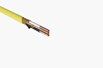
Type NM-B, Non-Metallic Sheathed Cable
Non-Metallic Sheathed Cable, PVC Insulation & Nylon Cover, PVC Jacket, 600V – Copper
Jacket is color coded for visual identification of conductors. Used in residential wiring as
branch circuits for outlets, switches, and other loads. For both exposed and concealed work
in normally dry locations except as prohibited by NEC®. To be installed or fished in air voids
in masonry block or tile walls, which are not subject to excessive wetness or dampness. The
allowable ampacity shall not exceed that of a 60°C rated conductor, in accordance with
NEC®.
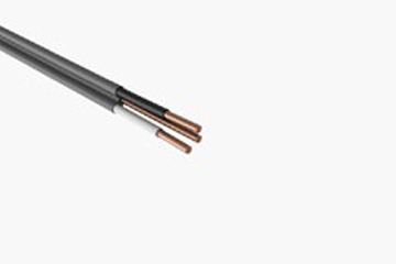
Type UF-B, Underground Feeder Cable
PVC Insulation & Nylon Cover, PVC Jacket, Ground, 600V – Copper
For use underground, including direct burial in the earth. For wiring in wet, dry, or corrosive
locations under the recognized wiring methods of the NEC®. Multiconductor can be installed
as non-metallic sheathed cable. Where so installed, installation and conductor
requirements shall comply with Parts II and III of Article 334. The allowable ampacity shall
not exceed that of a 60°C rated conductor, in accordance with NEC®.
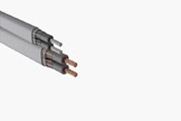
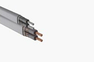
Type SEU, Service Entrance Cable
XLPE Insulation, PVC Jacket, 600V – Copper
Used as a service entry cable, to convey power from the service drop to the meter. Also in
other branch circuits or feeders as permitted by NEC®.
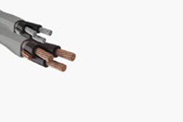
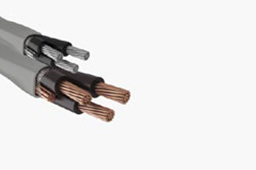
Type SER, Service Entrance Cable
XHHW/XHHW-2, XLPE Insulation, PVC Jacket, 600V – Copper
Used as a service entry cable, to convey power from the service drop to the meter. Also in
other branch circuits or feeders as permitted by NEC®.
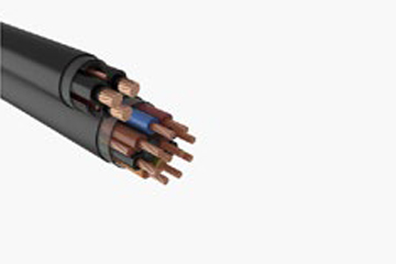
TC-THHN/THWN-2
PVC Insulation & Nylon Cover, PVC Jacket, VW-1, SR, ER, FT4, Dir. Bur., 600V – Copper
Specifically approved for power, control, lighting and signal circuits, in manufacturing,
industrial and commercial installations. For use in accordance with NEC®, Article 336, in
cable trays, in raceways, or where supported in outdoor locations supported by a messenger
wire.
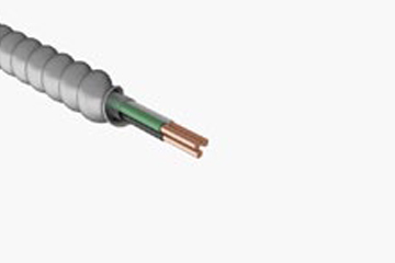
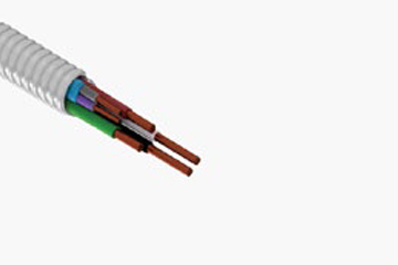
Type MC
THHN/THWN-2, Singles, PVC Insulation & Nylon Cover, Green Insulated Ground, 600V – Copper
For services, feeders, and branch circuits. For power, lighting, control and signal circuits.
Exposed or concealed. In cable tray and approved raceway. In dry locations and embedded
in plaster finish on brick or other mansonry except in damp or wet locations. Per NEC®
300.22 (C), in environmental air-handling spaces. Class I Div. 2, Class II Div 2, and Class III
Div hazardous locations, in accordance with NEC®.
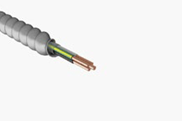
Type MC
THHN/THWN-2, Singles, PVC Insulation & Nylon Cover, Green Insulated Ground & Additional Isolated Ground, 600V – Copper
Where a redundant or isolated grounding paths are required. For services, feeders, and branch circuits. For power, lighting, control and signal circuits. Exposed or concealed. In cable tray and approved raceway. In dry locations and embedded in plaster finish on brick or other mansonry except in damp or wet locations. Per NEC® 300.22 (C), in environmental air-handling spaces. Class I Div. 2, Class II Div. 2, and Class III Div. 1 hazardous locations, in accordance with NEC®.
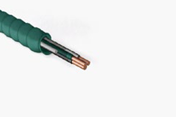
Type MC-HCF-AIA
Aluminum Bonding Wire in Contact with Armor, PVC Insulation & Nylon Cover, Green Armor, 600V – Copper
For installations requiring redundant, dedicated or isolated grounding paths. Used in health
care facilities for branch circuit wiring in patient care areas of hospitals, medical centers,
nursing homes, dental offices, clinics, outpatient facilites and other health care facilities in
accordance with NEC® Articles 517, 330 and 300.4 as applicable. (Note: Use in hazardous
anesthetizing areas is not permitted.) For places of assemblies and theaters per NEC®
Articles 518 and 520, respectively. In cable tray and approved raceways. In dry locations and
embedded in plaster finish on brick or other masonry except in damp or wet locations. Per
NEC® 300.22 (C), in environmental air-handling spaces. Class I Div. 2, Class II Div. 2, and
Class III Div. 1 hazardous locations, in accordance with NEC®. Requires use of UL Listed MCI-A fittings.
Type MC-PCS-AIA
Jacketed Pair Signal Cable under AIA Armor, PVC Insulation & Nylon Cover, 600V – Copper
For services, feeders, and branch circuits. Suitable for power, lighting, control, and signal
circuits requiring the use of signal cable in multi-residential, commercial, institutional and
industrial applications. Ideal for luminary or LED controls and for SMART buildings. Exposed
or concealed. In cable tray an approved raceway. In dry locations and embedded in plaster
finish on brick or other masonry except in damp or wet locations. Per NEC® 300.22 (C), in
environmental air-handling spaces. Class I Div. 2, Class II Div. 2, and Class III Div. 1
hazardous locations, in accordance with NEC®.
THHN/THWN-2
PVC Insulation, Nylon Jacket, 600V – Copper
Insulation and jacket is color coded for visual identification of conductors, and all colors are suitable for use in general purpose wiring in accordance with the requirements of NFPA 70 (NEC®). Approved for use at a maximum voltage of 600 volts and a maximum conductor temperature of 90°C in wet or dry locations and 75°C when exposed to gasoline and oil. Also rated AWM, for 105°C dry and 80°C in oil.
Aluminum Conductor
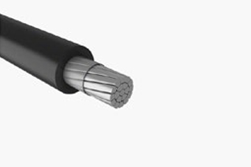
XHHW/XHHW-2
XLPE Insulation, 600/1000V – AA-8000 Aluminum
Used for general purpose wiring in circuits not exceeding 600 or 1000 volts as
indicated for the sizes. May be used in wet or dry locations, installed in conduit, duct,
or open air.
Physical Data
| XHHW/XHHW-2 600/1000 V | ||||
|---|---|---|---|---|
| Size AWG or kcmil |
Number of Strands |
Insulation Thickness |
Approximate Outside Diameter |
Approximate Net Weight |
| mil | in | lb/kft | ||
| 6 | 7 | 45 | 0.26 | 40 |
| 4 | 7 | 45 | 0.31 | 59 |
| 2 | 7 | 45 | 0.36 | 87 |
| 1 | 19 | 55 | 0.41 | 110 |
| 1/0 | 19 | 55 | 0.45 | 134 |
| 2/0 | 19 | 55 | 0.49 | 165 |
| 3/0 | 19 | 55 | 0.54 | 202 |
| 4/0 | 19 | 55 | 0.59 | 249 |
| 250 | 37 | 65 | 0.66 | 295 |
| 300 | 37 | 65 | 0.71 | 348 |
| 350 | 37 | 65 | 0.75 | 400 |
| 400 | 37 | 65 | 0.8 | 452 |
| 500 | 37 | 65 | 0.87 | 555 |
| 600 | 61 | 80 | 0.98 | 672 |
| 750 | 61 | 80 | 1.08 | 827 |
| 900 | 61 | 80 | 1.17 | 1000 |
| 1000 | 61 | 80 | 1.23 | 1082 |
| The above data are approximate and subject to normal manufacturing tolerances. Other sizes available upon request. | ||||
Ampacity Data
| XHHW/XHHW-2, RHH/RHW-2, SIS, USE-2, RW90, RWU90 | ||
|---|---|---|
| Conductor Size AWG/kcmil |
75 °C (167 °F) |
90 °C (194 °F) |
| 6 | 50 | 55 |
| 4 | 65 | 75 |
| 3 | 75 | 85 |
| 2 | 90 | 100 |
| 1 | 100 | 115 |
| 1/0 | 120 | 135 |
| 2/0 | 135 | 150 |
| 3/0 | 155 | 175 |
| 4/0 | 180 | 205 |
| 250 | 205 | 230 |
| 300 | 230 | 260 |
| 350 | 250 | 280 |
| 400 | 270 | 305 |
| 500 | 310 | 350 |
| 600 | 340 | 385 |
| 700 | 375 | 425 |
| 750 | 385 | 435 |
| 800 | 395 | 445 |
| 900 | 425 | 480 |
| 1000 | 445 | 500 |
| 1250 | 485 | 545 |
| 1500 | 520 | 585 |
| 1750 | 545 | 615 |
| 2000 | 560 | 630 |
| NEC Table 310.15(B)(16) (formerly Table 310.16) Allowable Ampacities of Insulated Conductors Rated Up to and Including 2000 V, 60 °C Through 90 °C (140 °F Through 194 °F), Not More Than Three Current-Carrying Conductors in Raceway, Cable, or Earth (Directly Buried), Based on Ambient Temperature of 30 °C (86 °F). | ||
| XHHW/XHHW-2, RHH/RHW-2, SIS, USE-2, RW90, RWU90 (cont.) | ||
|---|---|---|
| Conductor Size AWG/kcmil |
75 °C (167 °F) |
90 °C (194 °F) |
| 6 | 75 | 85 |
| 4 | 100 | 115 |
| 3 | 115 | 130 |
| 2 | 135 | 150 |
| 1 | 155 | 175 |
| 1/0 | 180 | 205 |
| 2/0 | 210 | 235 |
| 3/0 | 240 | 270 |
| 4/0 | 280 | 315 |
| 250 | 315 | 355 |
| 300 | 350 | 395 |
| 350 | 395 | 445 |
| 400 | 425 | 480 |
| 500 | 485 | 545 |
| 600 | 545 | 615 |
| 700 | 595 | 670 |
| 750 | 620 | 700 |
| 800 | 645 | 725 |
| 900 | 700 | 790 |
| 1000 | 750 | 845 |
| 1250 | 855 | 965 |
| 1500 | 950 | 1070 |
| 1750 | 1050 | 1185 |
| 2000 | 1150 | 1295 |
| NEC Table 310.15(B)(17) (formerly Table 310.17) Allowable Ampacities of Single Insulated Conductors Rated Up to and Including 2000 V in Free Air, Based on Ambient Temperature of 30 °C (86 °F). | ||
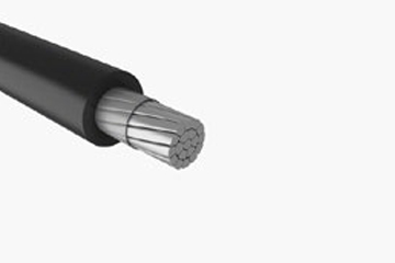
XHHW/XHHW-2 CT
XLPE Insulation, VW-1, GRI & GRII, SR, 600/1000V – AA-8000 Aluminum
Used for general purpose wiring in circuits not exceeding 600 or 1000 volts as
indicated for the sizes. May be used in wet or dry locations, installed in conduit, duct,
or open air.
Physical Data
| XHHW/XHHW-2 600/1000 V | ||||
|---|---|---|---|---|
| Size AWG or kcmil |
Number of Strands |
Insulation Thickness |
Approximate Outside Diameter |
Approximate Net Weight |
| mil | in | lb/kft | ||
| 6 | 7 | 45 | 0.26 | 43 |
| 4 | 7 | 45 | 0.31 | 62 |
| 2 | 7 | 45 | 0.36 | 92 |
| 1 | 19 | 55 | 0.41 | 116 |
| 1/0 | 19 | 55 | 0.45 | 140 |
| 2/0 | 19 | 55 | 0.49 | 170 |
| 3/0 | 19 | 55 | 0.54 | 208 |
| 4/0 | 19 | 55 | 0.59 | 255 |
| 250 | 37 | 65 | 0.66 | 307 |
| 300 | 37 | 65 | 0.71 | 360 |
| 350 | 37 | 65 | 0.75 | 413 |
| 400 | 37 | 65 | 0.8 | 466 |
| 500 | 37 | 65 | 0.87 | 570 |
| 600 | 61 | 80 | 0.98 | 699 |
| 750 | 61 | 80 | 1.08 | 856 |
| 900 | 61 | 80 | 1.17 | 1000 |
| 1000 | 61 | 80 | 1.23 | 1116 |
| The above data are approximate and subject to normal manufacturing tolerances. Other sizes available upon request. | ||||
Ampacity Data
| XHHW/XHHW-2, RHH/RHW-2, SIS, USE-2, RW90, RWU90 | ||
|---|---|---|
| Conductor Size AWG/kcmil |
75 °C (167 °F) |
90 °C (194 °F) |
| 6 | 50 | 55 |
| 4 | 65 | 75 |
| 3 | 75 | 85 |
| 2 | 90 | 100 |
| 1 | 100 | 115 |
| 1/0 | 120 | 135 |
| 2/0 | 135 | 150 |
| 3/0 | 155 | 175 |
| 4/0 | 180 | 205 |
| 250 | 205 | 230 |
| 300 | 230 | 260 |
| 350 | 250 | 280 |
| 400 | 270 | 305 |
| 500 | 310 | 350 |
| 600 | 340 | 385 |
| 700 | 375 | 425 |
| 750 | 385 | 435 |
| 800 | 395 | 445 |
| 900 | 425 | 480 |
| 1000 | 445 | 500 |
| 1250 | 485 | 545 |
| 1500 | 520 | 585 |
| 1750 | 545 | 615 |
| 2000 | 560 | 630 |
| NEC Table 310.15(B)(16) (formerly Table 310.16) Allowable Ampacities of Insulated Conductors Rated Up to and Including 2000 V, 60 °C Through 90 °C (140 °F Through 194 °F), Not More Than Three Current-Carrying Conductors in Raceway, Cable, or Earth (Directly Buried), Based on Ambient Temperature of 30 °C (86 °F). | ||
| XHHW/XHHW-2, RHH/RHW-2, SIS, USE-2, RW90, RWU90 (cont.) | ||
|---|---|---|
| Conductor Size AWG/kcmil |
75 °C (167 °F) |
90 °C (194 °F) |
| 6 | 75 | 85 |
| 4 | 100 | 115 |
| 3 | 115 | 130 |
| 2 | 135 | 150 |
| 1 | 155 | 175 |
| 1/0 | 180 | 205 |
| 2/0 | 210 | 235 |
| 3/0 | 240 | 270 |
| 4/0 | 280 | 315 |
| 250 | 315 | 355 |
| 300 | 350 | 395 |
| 350 | 395 | 445 |
| 400 | 425 | 480 |
| 500 | 485 | 545 |
| 600 | 545 | 615 |
| 700 | 595 | 670 |
| 750 | 620 | 700 |
| 800 | 645 | 725 |
| 900 | 700 | 790 |
| 1000 | 750 | 845 |
| 1250 | 855 | 965 |
| 1500 | 950 | 1070 |
| 1750 | 1050 | 1185 |
| 2000 | 1150 | 1295 |
| NEC Table 310.15(B)(17) (formerly Table 310.17) Allowable Ampacities of Single Insulated Conductors Rated Up to and Including 2000 V in Free Air, Based on Ambient Temperature of 30 °C (86 °F). | ||
Type SEU, Service Entrance Cable
XLPE Insulation, PVC Jacket, 600V – Aluminum
Used as a service entry cable, to convey power from the service drop to the meter.
Also in other branch circuits or feeders as permitted by NEC®.
Type SER, Service Entrance Cable
XHHW/XHHW-2, XLPE Insulation, PVC Jacket, 600V – Aluminum
Used as a service entry cable, to convey power from the service drop to the meter.
Also in other branch circuits or feeders as permitted by NEC®.
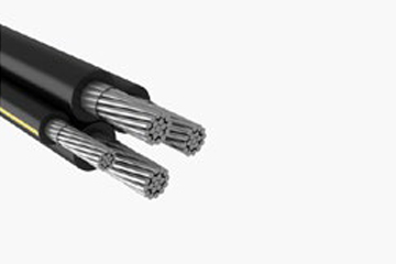
Secondary URD
Underground, Single/Triplex/Quadruplex, XLPE Insulated, 600V – Aluminum
Used for secondary distribution and underground service at 600 volts or less. May be
used in ducts or direct burial.
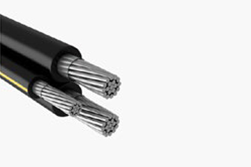
Secondary URD AA-8000, Tri-Rated
Underground, Triplex, Compressed Conductor, XLPE Insulation, 600V – Aluminum
Used for secondary distribution and underground service at 600 volts or less. AA-
8000 series aluminum alloy conductor is used for increased fliexibility. May be used
in ducts or direct burial.
Secondary URD AA-8000, Tri-Rated, Mobile Home
Feeder, Underground, Compact Conductor, XLPE Insulation, 600V – Aluminum
Designed to connect mobile homes to an electrical supply where permanent wiring is
required. Can also be used for general purpose wiring in circuits not exceeding 600
volts. May be used in wet or dry locations, installed in conduit, duct, and directly
buried in earth not exceeeding 90°C in accordance with requirements of the NEC®.