Grounding & Static Wire
Composite Conductor
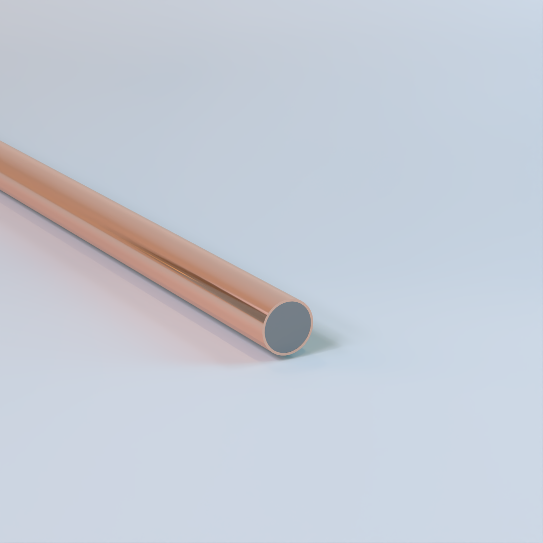
Bare Copper-Clad Steel (CCS) Conductor
Solid (Single End), Drawn Steel Alloy (DSA) Core, Metallurgically Bonded Copper Cladding, 39 AWG – 0 AWG, 40%, 30%, or 21% Conductivity, Hard-Drawn or Annealed, Low Carbon (LC), High Strength (HS), or Extra High Strength (EHS) Steel Core – Composite
Used for grounding and utility applications. Commonly specified for grounding elctrodes, counterpoise grounding systems, utility grounding and overhead static or shield wire applications where permitted by the National Electrical Code (NEC). Also available with a camoflauge (theft-deterrent) finish or PVC covering. Availability of conductivity class, temper, steel core strength, and finish varies by size and specification. Available from Copperweld®.
Physical Data
| CCS Conductor – Single End | ||||||||||
|---|---|---|---|---|---|---|---|---|---|---|
| AWG | Diameter | Nominal Break Load (lbf) | Weight (lb/1000’) |
Maximum DC Resistance at 20° C (Ω/1000’) |
Cross Sectional Area |
|||||
| Low Carbon (LC) |
(cmil) | mm2 | ||||||||
| (in) | (mm) | 40% | 30% | 40% | 30% | 40% | 30% | |||
| 2 | 0.2576 | 6.543 | 2606 | 2606 | 186.1 | 184.1 | 0.4108 | 0.5477 | 66358 | 33.62 |
| 3 | 0.2294 | 5.827 | 2067 | 2067 | 147.6 | 146 | 0.518 | 0.6569 | 52624 | 26.67 |
| 4 | 0.2043 | 5.189 | 1639 | 1639 | 117 | 115.8 | 0.6532 | 0.8708 | 41738 | 21.15 |
| 5 | 0.1819 | 4.62 | 1261 | 1261 | 92.8 | 91.8 | 0.8239 | 1.0985 | 33088 | 16.77 |
| 6 | 0.162 | 4.115 | 1031 | 1031 | 73.6 | 72.8 | 1.0388 | 1.3849 | 26244 | 13.3 |
| 7 | 0.1443 | 3.665 | 818 | 818 | 58.4 | 57.8 | 1.3092 | 1.7455 | 20822 | 10.55 |
| 8 | 0.1285 | 3.264 | 648 | 648 | 46.3 | 45.8 | 1.651 | 2.2011 | 16512 | 8.37 |
| 9 | 0.1144 | 2.906 | 514 | 514 | 36.7 | 36.3 | 2.083 | 2.7772 | 13087 | 6.63 |
| 10 | 0.1019 | 2.588 | 408 | 408 | 29.1 | 28.8 | 2.6254 | 3.5003 | 10384 | 5.26 |
| 12 | 0.0808 | 2.052 | 256 | 256 | 18.3 | 18.1 | 4.1336 | 5.511 | 6529 | 3.31 |
| 13 | 0.072 | 1.829 | 204 | 204 | 14.5 | 14.4 | 5.2058 | 6.9405 | 5184 | 2.63 |
| 14 | 0.0641 | 1.628 | 161 | 161 | 11.5 | 11.4 | 6.5681 | 8.7567 | 4109 | 2.08 |
| 15 | 0.0571 | 1.45 | 128 | 128 | 9.1 | 9 | 8.2772 | 11.0353 | 3260 | 1.65 |
| 16 | 0.0508 | 1.29 | 101 | 101 | 7.2 | 7.2 | 10.4575 | 13.9421 | 2581 | 1.31 |
| 17 | 0.0453 | 1.151 | 63 | 71 | 5.8 | 5.7 | 13.1509 | 17.5331 | 2052 | 1.04 |
| 18 | 0.0403 | 1.024 | 64 | 64 | 4.6 | 4.5 | 16.6166 | 22.1536 | 1624 | 0.82 |
| 19 | 0.0359 | 0.912 | 51 | 51 | 3.6 | 3.6 | 20.9394 | 27.9168 | 1289 | 0.65 |
| 20 | 0.032 | 0.813 | 40 | 40 | 2.9 | 2.8 | 26.3544 | 35.1362 | 1024 | 0.52 |
| 21 | 0.0285 | 0.724 | 32 | 32 | 2.3 | 2.3 | 33.2249 | 44.2961 | 812 | 0.41 |
| 22 | 0.0253 | 0.643 | 25 | 25 | 1.8 | 1.8 | 42.1611 | 56.2101 | 640 | 0.32 |
| 23 | 0.0226 | 0.574 | 20 | 20 | 1.4 | 1.4 | 52.8368 | 70.4431 | 511 | 0.26 |
| 24 | 0.0201 | 0.511 | 16 | 16 | 1.1 | 1.1 | 66.7977 | 89.056 | 404 | 0.21 |
| The above data are approximate and subject to normal manufacturing tolerances. | ||||||||||
| CCS 40% – Hard Drawn | |||||||||
|---|---|---|---|---|---|---|---|---|---|
| AWG | Diameter | Cross Sectional Area |
(cmil) | Weight (lbs/kft) |
Nominal Copper Thickness (in) |
Nominal DC Resistance (Ω/kft) |
ASTM Break Load (lbf) | ||
| in | in2 | Low Carbon (LC) |
High Strength (HS) |
Extra High Strength (EHS) |
|||||
| 0 | 0.3249 | 0.082907 | 105560 | 296 | 0.03249 | 0.246 | 4826 | 6757 | 9331 |
| 1 | 0.2893 | 0.065733 | 83694 | 234.7 | 0.02893 | 0.31 | 4273 | 5804 | 7781 |
| 2 | 0.2576 | 0.052117 | 66358 | 186.1 | 0.02576 | 0.391 | 3691 | 4905 | 6624 |
| 3 | 0.2294 | 0.041331 | 52624 | 147.6 | 0.02294 | 0.493 | 3088 | 4090 | 5414 |
| 4 | 0.2043 | 0.032781 | 41738 | 117 | 0.02043 | 0.621 | 2640 | 3435 | 4548 |
| 5 | 0.1819 | 0.025987 | 33088 | 92.77 | 0.01819 | 0.784 | 2143 | 2849 | 3782 |
| 6 | 0.162 | 0.020612 | 26244 | 73.58 | 0.0162 | 0.988 | 1740 | 2360 | 3100 |
| 7 | 0.1443 | 0.016354 | 20822 | 58.38 | 0.01443 | 1.245 | 1460 | 1952 | 2539 |
| 8 | 0.1285 | 0.012969 | 16512 | 46.3 | 0.01285 | 1.57 | 1183 | 1611 | 2139 |
| 9 | 0.1144 | 0.010279 | 13087 | 36.7 | 0.01144 | 1.981 | 967 | 1326 | 1795 |
| 10 | 0.1019 | 0.008155 | 10384 | 29.11 | 0.01019 | 2.497 | 815 | 1097 | 1488 |
| 11 | 0.0907 | 0.006461 | 8226 | 23.07 | 0.00907 | 3.152 | 665 | 887 | 1011 |
| 12 | 0.0808 | 0.005128 | 6529 | 18.31 | 0.00808 | 3.972 | 444 | 601 | 849 |
| 13 | 0.072 | 0.004072 | 5184 | 14.54 | 0.0072 | 5.002 | 362 | 497 | 637 |
| 14 | 0.0641 | 0.003227 | 4109 | 11.52 | 0.00641 | 6.311 | 298 | 410 | 535 |
| 15 | 0.0571 | 0.002561 | 3260 | 9.142 | 0.00571 | 7.953 | 228 | 300 | 424 |
| 16 | 0.0508 | 0.002027 | 2581 | 7.236 | 0.00508 | 10.05 | 187 | 247 | 348 |
| 17 | 0.0453 | 0.001612 | 2052 | 5.754 | 0.00453 | 12.64 | 155 | 205 | 294 |
| 18 | 0.0403 | 0.001276 | 1624 | 4.554 | 0.00403 | 15.97 | 130 | 169 | 232 |
| 19 | 0.0359 | 0.001012 | 1289 | 3.614 | 0.00359 | 20.12 | 98 | 133 | 196 |
| 20 | 0.032 | 0.000804 | 1024 | 2.871 | 0.0032 | 25.32 | 82 | 110 | 147 |
| 21 | 0.0285 | 0.000638 | 812 | 2.277 | 0.00285 | 31.92 | 65 | 88 | 125 |
| 22 | 0.0253 | 0.000503 | 640 | 1.795 | 0.00253 | 40.51 | 51 | 69 | 108 |
| 23 | 0.0226 | 0.000401 | 511 | 1.432 | 0.00226 | 50.77 | 41 | 55 | 86 |
| 24 | 0.0201 | 0.000317 | 404 | 1.133 | 0.00201 | 64.18 | 34 | 46 | 73 |
| 25 | 0.0179 | 0.000252 | 320 | 0.898 | 0.00179 | 80.93 | * | * | * |
| 26 | 0.0159 | 0.0002 | 254 | 0.713 | 0.00159 | 102 | * | * | * |
| 27 | 0.0142 | 0.000158 | 202 | 0.565 | 0.00142 | 128.7 | * | * | * |
| 28 | 0.0126 | 0.000126 | 160 | 0.448 | 0.00126 | 162.3 | * | * | * |
| 29 | 0.0113 | 0.0001 | 127 | 0.355 | 0.00113 | 204.6 | * | * | * |
| 30 | 0.01 | 7.9E-5 | 101 | 0.282 | 0.001 | 258 | * | * | * |
| 31 | 0.0089 | 6.3E-5 | 80 | 0.223 | 0.00089 | 325.3 | * | * | * |
| 32 | 0.008 | 5.0E-5 | 63 | 0.177 | 0.0008 | 410.3 | * | * | * |
| 33 | 0.0071 | 3.9E-5 | 50 | 0.141 | 0.00071 | 517.3 | * | * | * |
| 34 | 0.0063 | 3.1E-5 | 40 | 0.111 | 0.00063 | 652.3 | * | * | * |
| 35 | 0.0056 | 2.5E-5 | 32 | 0.088 | 0.00056 | 822.4 | * | * | * |
| 36 | 0.005 | 2.0E-5 | 25 | 0.07 | 0.0005 | 1037 | * | * | * |
| 37 | 0.0045 | 1.6E-5 | 20 | 0.056 | 0.00045 | 1308 | * | * | * |
| 38 | 0.004 | 1.2E-5 | 16 | 0.044 | 0.0004 | 1649 | * | * | * |
| 39 | 0.0035 | 1.0E-5 | 12 | 0.035 | 0.00035 | 2080 | * | * | * |
| The above data are approximate and subject to normal manufacturing tolerances. *For more information on fine wire gauges please contact your Champion representative. |
|||||||||
| CCS 40% – Annealed | ||||||||
|---|---|---|---|---|---|---|---|---|
| AWG | Diameter | Cross Sectional Area |
(cmil) | Weight (lbs/kft) |
Nominal Copper Thickness (in) |
Nominal DC Resistance (Ω/kft) |
ASTM Break Load (lbf) | |
| in | in2 | Low Carbon (LC) |
High Strength (HS) |
|||||
| 0 | 0.3249 | 0.082907 | 105560 | 296 | 0.03249 | 0.246 | – | – |
| 1 | 0.2893 | 0.065733 | 83694 | 234.7 | 0.02893 | 0.31 | – | – |
| 2 | 0.2576 | 0.052117 | 66358 | 186.1 | 0.02576 | 0.391 | 2023 | 2275 |
| 3 | 0.2294 | 0.041331 | 52624 | 147.6 | 0.02294 | 0.493 | 1604 | 1805 |
| 4 | 0.2043 | 0.032781 | 41738 | 117 | 0.02043 | 0.621 | 1272 | 1431 |
| 5 | 0.1819 | 0.025987 | 33088 | 92.77 | 0.01819 | 0.784 | 1009 | 1135 |
| 6 | 0.162 | 0.020612 | 26244 | 73.58 | 0.0162 | 0.988 | 800 | 900 |
| 7 | 0.1443 | 0.016354 | 20822 | 58.38 | 0.01443 | 1.245 | 635 | 714 |
| 8 | 0.1285 | 0.012969 | 16512 | 46.3 | 0.01285 | 1.57 | 503 | 566 |
| 9 | 0.1144 | 0.010279 | 13087 | 36.7 | 0.01144 | 1.981 | 399 | 449 |
| 10 | 0.1019 | 0.008155 | 10384 | 29.11 | 0.01019 | 2.497 | 316 | 356 |
| 11 | 0.0907 | 0.006461 | 8226 | 23.07 | 0.00907 | 3.152 | 253 | 285 |
| 12 | 0.0808 | 0.005128 | 6529 | 18.31 | 0.00808 | 3.972 | 201 | 226 |
| 13 | 0.072 | 0.004072 | 5184 | 14.54 | 0.0072 | 5.002 | 160 | 180 |
| 14 | 0.0641 | 0.003227 | 4109 | 11.52 | 0.00641 | 6.311 | 127 | 142 |
| 15 | 0.0571 | 0.002561 | 3260 | 9.142 | 0.00571 | 7.953 | 100 | 113 |
| 16 | 0.0508 | 0.002027 | 2581 | 7.236 | 0.00508 | 10.05 | 79 | 89 |
| 17 | 0.0453 | 0.001612 | 2052 | 5.754 | 0.00453 | 12.64 | 63 | 71 |
| 18 | 0.0403 | 0.001276 | 1624 | 4.554 | 0.00403 | 15.97 | 50 | 56 |
| 19 | 0.0359 | 0.001012 | 1289 | 3.614 | 0.00359 | 20.12 | 40 | 45 |
| 20 | 0.032 | 0.000804 | 1024 | 2.871 | 0.0032 | 25.32 | 32 | 35 |
| 21 | 0.0285 | 0.000638 | 812 | 2.277 | 0.00285 | 31.92 | 25 | 31 |
| 22 | 0.0253 | 0.000503 | 640 | 1.795 | 0.00253 | 40.51 | 20 | 25 |
| 23 | 0.0226 | 0.000401 | 511 | 1.432 | 0.00226 | 50.77 | 16 | 20 |
| 24 | 0.0201 | 0.000317 | 404 | 1.133 | 0.00201 | 64.18 | 12 | 16 |
| 25 | 0.0179 | 0.000252 | 320 | 0.898 | 0.00179 | 80.93 | 10 | 12 |
| 26 | 0.0159 | 0.0002 | 254 | 0.713 | 0.00159 | 102 | 7.8 | 9.8 |
| 27 | 0.0142 | 0.000158 | 202 | 0.565 | 0.00142 | 128.7 | 6.2 | 7.8 |
| The above data are approximate and subject to normal manufacturing tolerances. | ||||||||
| CCS 30% – Hard Drawn | |||||||||
|---|---|---|---|---|---|---|---|---|---|
| AWG | Diameter | Cross Sectional Area |
(cmil) | Weight (lbs/kft) |
Nominal Copper Thickness (in) |
Nominal DC Resistance (Ω/kft) |
Low Carbon (LC) |
ASTM Break Load (lbf) | |
| in | in2 | High Strength (HS) |
Extra High Strength (EHS) |
||||||
| 0 | 0.3249 | 0.082907 | 105560 | 292.9 | 0.02274 | 0.327 | 5148 | 6998 | 10055 |
| 1 | 0.2893 | 0.065733 | 83694 | 232.2 | 0.02025 | 0.413 | 4592 | 6250 | 8865 |
| 2 | 0.2576 | 0.052117 | 66358 | 184.1 | 0.01803 | 0.521 | 3894 | 5309 | 7332 |
| 3 | 0.2294 | 0.041331 | 52624 | 146 | 0.01606 | 0.657 | 3288 | 4411 | 6055 |
| 4 | 0.2043 | 0.032781 | 41738 | 115.8 | 0.0143 | 0.828 | 2672 | 3817 | 4532 |
| 5 | 0.1819 | 0.025987 | 33088 | 91.81 | 0.01273 | 1.045 | 2219 | 3152 | 3795 |
| 6 | 0.162 | 0.020612 | 26244 | 72.82 | 0.01134 | 1.317 | 1840 | 2600 | 3150 |
| 7 | 0.1443 | 0.016354 | 20822 | 57.78 | 0.0101 | 1.66 | 1539 | 2142 | 2602 |
| 8 | 0.1285 | 0.012969 | 16512 | 45.82 | 0.009 | 2.094 | 1258 | 1762 | 2139 |
| 9 | 0.1144 | 0.010279 | 13087 | 36.31 | 0.00801 | 2.641 | 1027 | 1446 | 1736 |
| 10 | 0.1019 | 0.008155 | 10384 | 28.81 | 0.00713 | 3.329 | 847 | 1195 | 1416 |
| 11 | 0.0907 | 0.006461 | 8226 | 22.83 | 0.00635 | 4.202 | 687 | 975 | 1134 |
| 12 | 0.0808 | 0.005128 | 6529 | 18.11 | 0.00566 | 5.295 | 564 | 603 | 900 |
| 13 | 0.072 | 0.004072 | 5184 | 14.38 | 0.00504 | 6.669 | 407 | 507 | 714 |
| 14 | 0.0641 | 0.003227 | 4109 | 11.4 | 0.00449 | 8.414 | 312 | 402 | 566 |
| 15 | 0.0571 | 0.002561 | 3260 | 9.047 | 0.004 | 10.6 | 256 | 319 | 449 |
| 16 | 0.0508 | 0.002027 | 2581 | 7.16 | 0.00356 | 13.4 | 210 | 252 | 356 |
| 17 | 0.0453 | 0.001612 | 2052 | 5.694 | 0.00317 | 16.85 | 171 | 201 | 283 |
| 18 | 0.0403 | 0.001276 | 1624 | 4.506 | 0.00282 | 21.29 | 140 | 163 | 224 |
| 19 | 0.0359 | 0.001012 | 1289 | 3.576 | 0.00251 | 26.82 | 108 | 129 | 178 |
| 20 | 0.032 | 0.000804 | 1024 | 2.841 | 0.00224 | 33.76 | 88 | 106 | 141 |
| 21 | 0.0285 | 0.000638 | 812 | 2.254 | 0.002 | 42.56 | 70 | 79 | 154 |
| 22 | 0.0253 | 0.000503 | 640 | 1.776 | 0.00177 | 54.01 | 55 | 63 | 121 |
| 23 | 0.0226 | 0.000401 | 511 | 1.417 | 0.00158 | 67.68 | 47 | 50 | 99 |
| 24 | 0.0201 | 0.000317 | 404 | 1.121 | 0.00141 | 85.56 | 37 | 40 | 79 |
| 25 | 0.0179 | 0.000252 | 320 | 0.889 | 0.00125 | 107.9 | * | * | * |
| 26 | 0.0159 | 0.0002 | 254 | 0.705 | 0.00112 | 136 | * | * | * |
| 27 | 0.0142 | 0.000158 | 202 | 0.559 | 0.00099 | 171.5 | * | * | * |
| 28 | 0.0126 | 0.000126 | 160 | 0.443 | 0.00088 | 216.3 | * | * | * |
| 29 | 0.0113 | 0.0001 | 127 | 0.352 | 0.00079 | 272.8 | * | * | * |
| 30 | 0.01 | 7.9E-5 | 101 | 0.279 | 0.0007 | 344 | * | * | * |
| 31 | 0.0089 | 6.3E-5 | 80 | 0.221 | 0.00062 | 433.7 | * | * | * |
| 32 | 0.008 | 5.0E-5 | 63 | 0.175 | 0.00056 | 547 | * | * | * |
| 33 | 0.0071 | 3.9E-5 | 50 | 0.139 | 0.0005 | 689.7 | * | * | * |
| 34 | 0.0063 | 3.1E-5 | 40 | 0.11 | 0.00044 | 869.6 | * | * | * |
| 35 | 0.0056 | 2.5E-5 | 32 | 0.087 | 0.00039 | 1096 | * | * | * |
| 36 | 0.005 | 2.0E-5 | 25 | 0.069 | 0.00035 | 1383 | * | * | * |
| 37 | 0.0045 | 1.6E-5 | 20 | 0.055 | 0.00031 | 1743 | * | * | * |
| 38 | 0.004 | 1.2E-5 | 16 | 0.044 | 0.00028 | 2199 | * | * | * |
| 39 | 0.0035 | 1.0E-5 | 12 | 0.035 | 0.00025 | 2773 | * | * | * |
| The above data are approximate and subject to normal manufacturing tolerances. *For more information on fine wire gauges please contact your Champion representative. |
|||||||||
| CCS 30% – Annealed | ||||||||
|---|---|---|---|---|---|---|---|---|
| AWG | Diameter | Cross Sectional Area |
(cmil) | Weight (lbs/kft) |
Nominal Copper Thickness (in) |
Nominal DC Resistance (Ω/kft) |
ASTM Break Load (lbf) | |
| in | in2 | Low Carbon (LC) |
High Strength (HS) |
|||||
| 0 | 0.3249 | 0.082907 | 105560 | 292.9 | 0.02274 | 0.327 | – | – |
| 1 | 0.2893 | 0.065733 | 83694 | 232.2 | 0.02025 | 0.413 | – | – |
| 2 | 0.2576 | 0.052117 | 66358 | 184.1 | 0.01803 | 0.521 | 2275 | 2528 |
| 3 | 0.2294 | 0.041331 | 52624 | 146 | 0.01606 | 0.657 | 1805 | 2005 |
| 4 | 0.2043 | 0.032781 | 41738 | 115.8 | 0.0143 | 0.828 | 1431 | 1590 |
| 5 | 0.1819 | 0.025987 | 33088 | 91.81 | 0.01273 | 1.045 | 1135 | 1261 |
| 6 | 0.162 | 0.020612 | 26244 | 72.82 | 0.01134 | 1.317 | 900 | 1000 |
| 7 | 0.1443 | 0.016354 | 20822 | 57.78 | 0.0101 | 1.66 | 714 | 793 |
| 8 | 0.1285 | 0.012969 | 16512 | 45.82 | 0.009 | 2.094 | 566 | 629 |
| 9 | 0.1144 | 0.010279 | 13087 | 36.31 | 0.00801 | 2.641 | 449 | 499 |
| 10 | 0.1019 | 0.008155 | 10384 | 28.81 | 0.00713 | 3.329 | 356 | 396 |
| 11 | 0.0907 | 0.006461 | 8226 | 22.83 | 0.00635 | 4.202 | 285 | 317 |
| 12 | 0.0808 | 0.005128 | 6529 | 18.11 | 0.00566 | 5.295 | 226 | 251 |
| 13 | 0.072 | 0.004072 | 5184 | 14.38 | 0.00504 | 6.669 | 180 | 200 |
| 14 | 0.0641 | 0.003227 | 4109 | 11.4 | 0.00449 | 8.414 | 142 | 158 |
| 15 | 0.0571 | 0.002561 | 3260 | 9.047 | 0.004 | 10.6 | 113 | 125 |
| 16 | 0.0508 | 0.002027 | 2581 | 7.16 | 0.00356 | 13.4 | 89 | 99 |
| 17 | 0.0453 | 0.001612 | 2052 | 5.694 | 0.00317 | 16.85 | 71 | 79 |
| 18 | 0.0403 | 0.001276 | 1624 | 4.506 | 0.00282 | 21.29 | 56 | 63 |
| 19 | 0.0359 | 0.001012 | 1289 | 3.576 | 0.00251 | 26.82 | 45 | 50 |
| 20 | 0.032 | 0.000804 | 1024 | 2.841 | 0.00224 | 33.76 | 35 | 39 |
| 21 | 0.0285 | 0.000638 | 812 | 2.254 | 0.002 | 42.56 | 28 | 34 |
| 22 | 0.0253 | 0.000503 | 640 | 1.776 | 0.00177 | 54.01 | 22 | 27 |
| 23 | 0.0226 | 0.000401 | 511 | 1.417 | 0.00158 | 67.68 | 18 | 22 |
| 24 | 0.0201 | 0.000317 | 404 | 1.121 | 0.00141 | 85.56 | 14 | 17 |
| 25 | 0.0179 | 0.000252 | 320 | 0.889 | 0.00125 | 107.9 | 11 | 14 |
| 26 | 0.0159 | 0.0002 | 254 | 0.705 | 0.00112 | 136 | 9 | 11 |
| 27 | 0.0142 | 0.000158 | 202 | 0.559 | 0.00099 | 171.5 | 7 | 9 |
| The above data are approximate and subject to normal manufacturing tolerances. | ||||||||
| CCS 21% – Hard Drawn | ||||||||
|---|---|---|---|---|---|---|---|---|
| AWG | Diameter | Cross-Sectional Area |
(cmil) | Weight (lbs/kft) |
Nominal Copper Thickness (in) |
Nominal DC Resistance (Ω/kft) |
ASTM Break Load (lbf) |
|
| in | in2 | Low Carbon (LC) |
Extra High Strength (EHS) |
|||||
| 0 | 0.3249 | 0.082907 | 105,560 | 287.02 | 0.00975 | 0.468 | 6033 | 11664 |
| 1 | 0.2893 | 0.065733 | 83,694 | 227.57 | 0.00868 | 0.59 | 5293 | 9566 |
| 2 | 0.2576 | 0.052117 | 66,358 | 180.43 | 0.00773 | 0.744 | 4551 | 7989 |
| 3 | 0.2294 | 0.041331 | 52,624 | 143.09 | 0.00688 | 0.939 | 3810 | 6697 |
| 4 | 0.2043 | 0.032781 | 41,738 | 113.49 | 0.00613 | 1.183 | 3149 | 5502 |
| 5 | 0.1819 | 0.025987 | 33,088 | 89.97 | 0.00546 | 1.493 | 2622 | 4551 |
| 6 | 0.162 | 0.020612 | 26,244 | 71.36 | 0.00486 | 1.882 | 2160 | 3740 |
| 7 | 0.1443 | 0.016354 | 20,822 | 56.62 | 0.00433 | 2.372 | 1777 | 3142 |
| 8 | 0.1285 | 0.012969 | 16,512 | 44.9 | 0.00386 | 2.991 | 1447 | 2586 |
| 9 | 0.1144 | 0.010279 | 13,087 | 35.59 | 0.00343 | 3.774 | 1197 | 2144 |
| 10 | 0.1019 | 0.008155 | 10,384 | 28.23 | 0.00306 | 4.757 | 1005 | 1804 |
| 11 | 0.0907 | 0.006461 | 8,226 | 22.37 | 0.00272 | 6.004 | 826 | 1508 |
| 12 | 0.0808 | 0.005128 | 6,529 | 17.75 | 0.00242 | 7.565 | 578 | 867 |
| 13 | 0.072 | 0.004072 | 5,184 | 14.1 | 0.00216 | 9.527 | 475 | 717 |
| 14 | 0.0641 | 0.003227 | 4,109 | 11.17 | 0.00192 | 12.02 | 400 | 590 |
| 15 | 0.0571 | 0.002561 | 3,260 | 8.87 | 0.00171 | 15.15 | 307 | 493 |
| 16 | 0.0508 | 0.002027 | 2,581 | 7.02 | 0.00152 | 19.14 | 251 | 408 |
| 17 | 0.0453 | 0.001612 | 2,052 | 5.58 | 0.00136 | 24.07 | 206 | 337 |
| 18 | 0.0403 | 0.001276 | 1,624 | 4.42 | 0.00121 | 30.41 | 171 | 280 |
| 19 | 0.0359 | 0.001012 | 1,289 | 3.5 | 0.00108 | 38.32 | 129 | 236 |
| 20 | 0.032 | 0.000804 | 1,024 | 2.78 | 0.00096 | 48.23 | 108 | 177 |
| 21 | 0.0285 | 0.000644 | 820 | 2.23 | 0.00086 | 60.2 | 86 | 150 |
| 22 | 0.0253 | 0.000505 | 642 | 1.75 | 0.00076 | 76.88 | 68 | 127 |
| 23 | 0.0226 | 0.0004 | 509 | 1.39 | 0.00068 | 96.94 | 54 | 101 |
| 24 | 0.0201 | 0.000317 | 404 | 1.1 | 0.0006 | 122.2 | 45 | 84 |
| 25 | 0.0179 | 0.000252 | 320 | 0.87 | 0.00054 | 154.1 | * | * |
| 26 | 0.0159 | 0.0002 | 254 | 0.69 | 0.00048 | 194.4 | * | * |
| 27 | 0.0142 | 0.000158 | 202 | 0.55 | 0.00043 | 245.1 | * | * |
| 28 | 0.0126 | 0.000126 | 160 | 0.43 | 0.00038 | 309.1 | * | * |
| 29 | 0.0113 | 0.0001 | 127 | 0.34 | 0.00034 | 389.7 | * | * |
| 30 | 0.01 | 7.9E-5 | 101 | 0.27 | 0.0003 | 491.4 | * | * |
| 31 | 0.0089 | 6.3E-5 | 80 | 0.22 | 0.00027 | 619.6 | * | * |
| 32 | 0.008 | 5.0E-5 | 63 | 0.17 | 0.00024 | 781.5 | * | * |
| 33 | 0.0071 | 3.9E-5 | 50 | 0.14 | 0.00021 | 985.3 | * | * |
| 34 | 0.0063 | 3.1E-5 | 40 | 0.11 | 0.00019 | 1,242 | * | * |
| 35 | 0.0056 | 2.5E-5 | 32 | 0.09 | 0.00017 | 1,567 | * | * |
| 36 | 0.005 | 2.0E-5 | 25 | 0.07 | 0.00015 | 1,976 | * | * |
| 37 | 0.0045 | 1.6E-5 | 20 | 0.05 | 0.00013 | 2,491 | * | * |
| 38 | 0.004 | 1.2E-5 | 16 | 0.04 | 0.00012 | 3,142 | * | * |
| 39 | 0.0035 | 1.0E-5 | 12 | 0.03 | 0.00011 | 3,961 | * | * |
| The above data are approximate and subject to normal manufacturing tolerances. *For more information on fine wire gauges please contact your Champion representative. |
||||||||
| CCS 21% – Annealed | |||||||
|---|---|---|---|---|---|---|---|
| AWG | Diameter | Cross-Sectional Area |
(cmil) | Weight (lbs/kft) |
Nominal Copper Thickness (in) |
Nominal DC Resistance (Ω/kft) |
ASTM Break Load (lbf) |
| in | in2 | Low Carbon (LC) |
|||||
| 0 | 0.3249 | 0.08291 | 105560 | 287.02 | 0.00975 | 0.468 | – |
| 1 | 0.2893 | 0.06573 | 83694 | 227.57 | 0.00868 | 0.59 | – |
| 2 | 0.2576 | 0.05212 | 66358 | 180.43 | 0.00773 | 0.744 | 2528 |
| 3 | 0.2294 | 0.04133 | 52624 | 143.09 | 0.00688 | 0.939 | 2005 |
| 4 | 0.2043 | 0.03278 | 41738 | 113.49 | 0.00613 | 1.183 | 1590 |
| 5 | 0.1819 | 0.02599 | 33088 | 89.97 | 0.00546 | 1.493 | 1261 |
| 6 | 0.162 | 0.02061 | 26244 | 71.36 | 0.00486 | 1.882 | 1000 |
| 7 | 0.1443 | 0.01635 | 20822 | 56.62 | 0.00433 | 2.372 | 793 |
| 8 | 0.1285 | 0.01297 | 16512 | 44.9 | 0.00386 | 2.991 | 629 |
| 9 | 0.1144 | 0.01028 | 13087 | 35.59 | 0.00343 | 3.774 | 499 |
| 10 | 0.1019 | 0.00816 | 10384 | 28.23 | 0.00306 | 4.757 | 396 |
| 11 | 0.0907 | 0.00646 | 8226 | 22.37 | 0.00272 | 6.004 | 317 |
| 12 | 0.0808 | 0.00513 | 6529 | 17.75 | 0.00242 | 7.565 | 251 |
| 13 | 0.072 | 0.00407 | 5184 | 14.1 | 0.00216 | 9.527 | 200 |
| 14 | 0.0641 | 0.00323 | 4109 | 11.17 | 0.00192 | 12.02 | 158 |
| 15 | 0.0571 | 0.00256 | 3260 | 8.87 | 0.00171 | 15.15 | 125 |
| 16 | 0.0508 | 0.00203 | 2581 | 7.02 | 0.00152 | 19.14 | 99 |
| 17 | 0.0453 | 0.00161 | 2052 | 5.58 | 0.00136 | 24.07 | 79 |
| 18 | 0.0403 | 0.00128 | 1624 | 4.42 | 0.00121 | 30.41 | 63 |
| 19 | 0.0359 | 0.00101 | 1289 | 3.5 | 0.00108 | 38.32 | 50 |
| 20 | 0.032 | 0.0008 | 1024 | 2.78 | 0.00096 | 48.23 | 39 |
| 21 | 0.0285 | 0.00064 | 820 | 2.23 | 0.00086 | 60.2 | 32 |
| 22 | 0.0253 | 0.0005 | 642 | 1.75 | 0.00076 | 76.88 | 25 |
| 23 | 0.0226 | 0.0004 | 509 | 1.39 | 0.00068 | 76.88 | 20 |
| 24 | 0.0201 | 0.00032 | 404 | 1.1 | 0.0006 | 122.2 | 16 |
| 25 | 0.0179 | 0.00025 | 320 | 0.87 | 0.00054 | 154.1 | 12 |
| 26 | 0.0159 | 0.0002 | 254 | 0.69 | 0.00048 | 194.4 | 10 |
| 27 | 0.0142 | 0.00016 | 202 | 0.55 | 0.00043 | 245.1 | 8 |
| The above data are approximate and subject to normal manufacturing tolerances. | |||||||
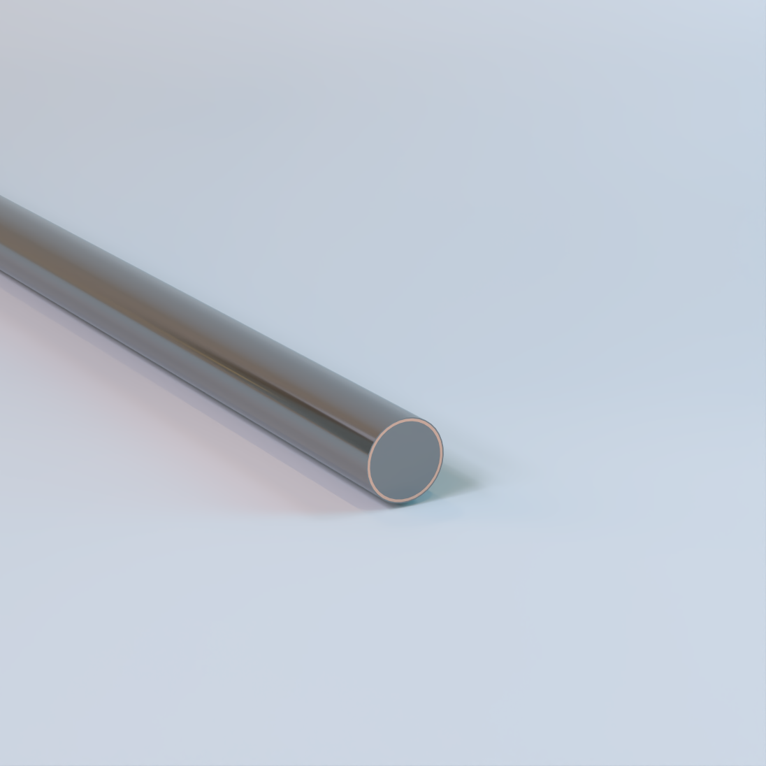
Copper-Clad Steel (CCS) Conductor with Camouflage Finish
Solid (Single End), Drawn Steel Alloy (DSA) Core, Metallurgically Bonded Copper Cladding, 39 AWG – 0 AWG, 40%, 30%, or 21% Conductivity, Hard-Drawn or Annealed, Low Carbon (LC), High Strength (HS), or Extra High Strength (EHS) Steel Core – Composite
Used for grounding and utility applications. Commonly specified for grounding elctrodes, counterpoise grounding systems, utility grounding and overhead static or shield wire applications where permitted by the National Electrical Code (NEC). Also available bare or with a PVC covering. Availability of conductivity class, temper, steel core strength, and finish varies by size and specification. Available from Copperweld®.
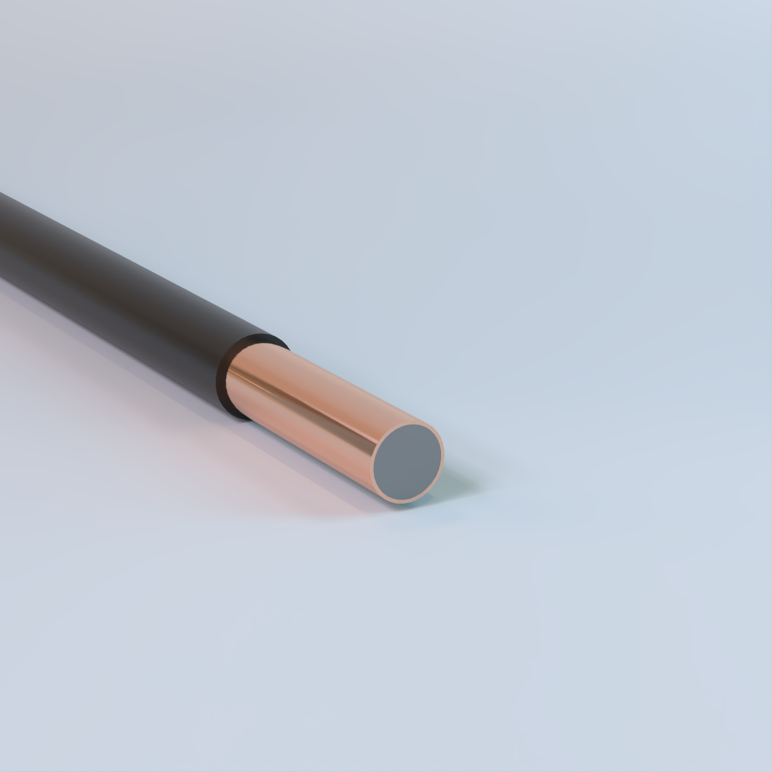
Copper-Clad Steel (CCS) Conductor with PVC Cover
Solid (Single End), Drawn Steel Alloy (DSA) Core, Metallurgically Bonded Copper Cladding, 39 AWG – 0 AWG, 40%, 30%, or 21% Conductivity, Hard-Drawn or Annealed, Low Carbon (LC), High Strength (HS), or Extra High Strength (EHS) Steel Core – Composite
Used for grounding and utility applications. Commonly specified for grounding elctrodes, counterpoise grounding systems, utility grounding and overhead static or shield wire applications where permitted by the National Electrical Code (NEC). Also available bare or with a camouflage (theft-deterrent) finish. Availability of conductivity class, temper, steel core strength, and finish varies by size and specification. Available from Copperweld®.
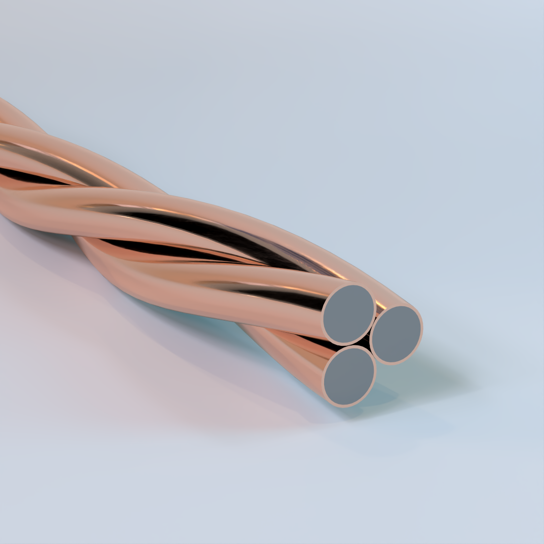
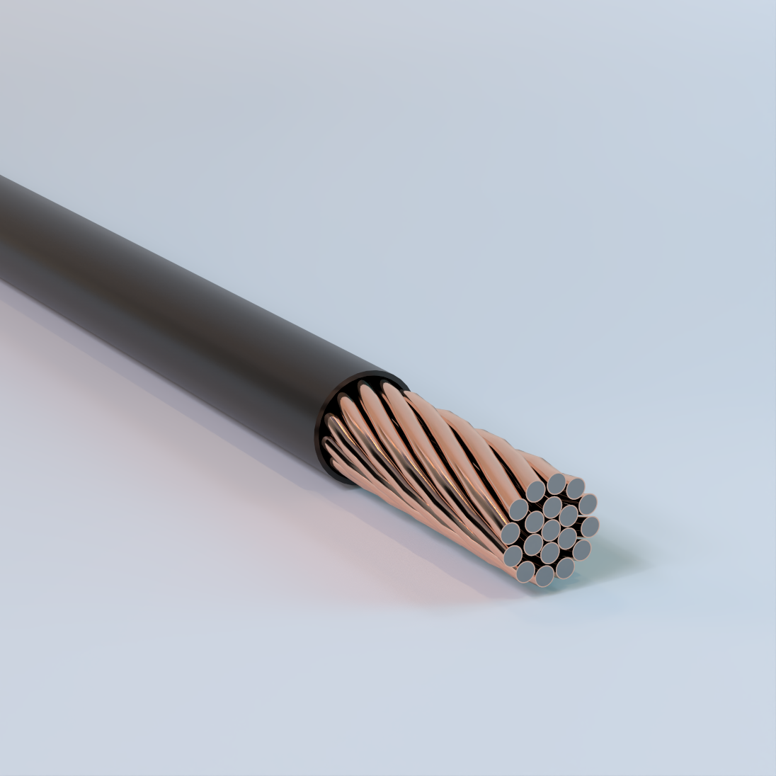
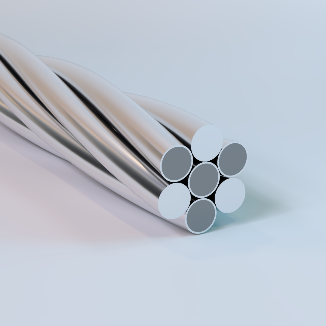
Bare Copper-Clad Steel (CCS) Conductor
Concentric Lay Stranded, Drawn Steel Alloy (DSA) Core, Metallurgically Bonded Copper Cladding, 3 Strand, 40% or 30% Conductivity, Annealed; Low Carbon (LC), High Strength (HS), or Extra High Strength (EHS) Steel Core – Composite
Used for grounding and utility applications. Commonly specified for grounding systems, counterpoise grounding, utility grounding, overhead static or shield wire applications, and associated bonding within grounding systems where permitted by the National Electrical Code (NEC). Also available with a camouflage (theft-deterrent) finish or PVC covering. Availability of strand construction, conductivity class, steel core strength, and finish varies by size and specification. Available from Copperweld® under the Century™ product line.
Physical Data
| CCS Conductor – Concentric Lay Stranded | ||||||||||
|---|---|---|---|---|---|---|---|---|---|---|
| AWG | Diameter | Nominal Break Load (lbf) |
Weight (lb/1000’) |
Maximum DC Resistance at 20° C (Ω/1000’) |
Cross Sectional Area |
|||||
| (in) | (mm) | Low Carbon (LC) |
40% | 30% | 40% | 30% | (cmil) | mm2 | ||
| 40% | 30% | |||||||||
| 19-Strand Cable | ||||||||||
| 19 No. 5 | 0.91 | 23.1 | 22219 | 22219 | 1787 | 1769 | 0.044 | 0.0586 | 628665 | 318.55 |
| 19 No. 6 | 0.81 | 20.57 | 17623 | 17623 | 1418 | 1403 | 0.0554 | 0.0739 | 498636 | 252.66 |
| 19 No. 7 | 0.722 | 18.33 | 13983 | 13983 | 1125 | 1113 | 0.0699 | 0.0932 | 395627 | 200.47 |
| 19 No. 8 | 0.643 | 16.32 | 11088 | 11088 | 892 | 883 | 0.0881 | 0.1175 | 313733 | 158.97 |
| 19 No. 9 | 0.572 | 14.53 | 8788 | 8788 | 707 | 700 | 0.1112 | 0.1482 | 248660 | 126 |
| 19 No. 10 | 0.51 | 12.94 | 6973 | 6973 | 561 | 555 | 0.1401 | 0.1868 | 197289 | 99.97 |
7-Strand Cable |
||||||||||
| 7 No. 4 | 0.613 | 15.57 | 10326 | 10326 | 827 | 819 | 0.0942 | 0.1256 | 292169 | 148.04 |
| 7 No. 5 | 0.546 | 13.86 | 8186 | 8186 | 656 | 649 | 0.1189 | 0.1585 | 231613 | 117.36 |
| 7 No. 6 | 0.486 | 12.34 | 6493 | 6493 | 520 | 515 | 0.1499 | 0.1998 | 183708 | 93.09 |
| 7 No. 7 | 0.433 | 11 | 5151 | 5151 | 413 | 408 | 0.1889 | 0.2519 | 145757 | 73.86 |
| 7 No. 8 | 0.386 | 9.79 | 4085 | 4085 | 327 | 324 | 0.2382 | 0.3176 | 115586 | 58.57 |
| 7 No. 9 | 0.343 | 8.72 | 3238 | 3238 | 259 | 257 | 0.3006 | 0.4007 | 91612 | 46.42 |
| 7 No. 10 | 0.306 | 7.76 | 2569 | 2569 | 206 | 204 | 0.3788 | 0.505 | 72685 | 36.83 |
| 7 No. 12 | 0.242 | 6.16 | 1615 | 1615 | 129 | 128 | 0.5964 | 0.7952 | 45700 | 23.16 |
3-Strand Cable |
||||||||||
| 3 No. 4 | 0.44 | 11.18 | 4671 | 4671 | 354 | 350 | 0.2195 | 0.2926 | 125215 | 63.45 |
| 3 No. 5 | 0.392 | 9.96 | 3703 | 3703 | 281 | 278 | 0.2768 | 0.3691 | 99263 | 50.3 |
| 3 No. 6 | 0.349 | 8.87 | 2937 | 2937 | 223 | 220 | 0.349 | 0.4653 | 78732 | 39.89 |
| 3 No. 7 | 0.311 | 7.9 | 2330 | 2330 | 177 | 175 | 0.4399 | 0.5865 | 62467 | 31.65 |
| 3 No. 8 | 0.277 | 7.03 | 1848 | 1848 | 140 | 139 | 0.5547 | 0.7396 | 49537 | 25.1 |
| 3 No. 9 | 0.247 | 6.26 | 1465 | 1465 | 111 | 110 | 0.6999 | 0.9331 | 39262 | 19.89 |
| 3 No. 10 | 0.22 | 5.58 | 1162 | 1162 | 88 | 87 | 0.8821 | 1.1761 | 31151 | 15.78 |
| 3 No. 12 | 0.174 | 4.42 | 731 | 731 | 55 | 55 | 1.3889 | 1.8517 | 19586 | 9.92 |
| Break load of 7-wire and 19-wire copper-clad steel cables are taken as 90% of the sum of the break loads of the individual wires. Break load of 3-wire copper-clad steel cables are taken as 95% of the sum of the break loads of the individual wires. The above data are approximate and subject to normal manufacturing tolerances. |
||||||||||
| CCS 40% – Hard Drawn | |||||||||
|---|---|---|---|---|---|---|---|---|---|
| AWG | Diameter | Cross Sectional Area |
(cmil) | Weight (lbs/kft) |
Nominal Copper Thickness (in) |
Nominal DC Resistance (Ω/kft) |
ASTM Break Load (lbf) | ||
| (in) | in2
| Low Carbon |
(LC) High |
Strength (HS) Extra High |
Strength (EHS) | |||||
| 0 | 0.3249 | 0.082907 | 105560 | 296 | 0.03249 | 0.246 | 4826 | 6757 | 9331 |
| 1 | 0.2893 | 0.065733 | 83694 | 234.7 | 0.02893 | 0.31 | 4273 | 5804 | 7781 |
| 2 | 0.2576 | 0.052117 | 66358 | 186.1 | 0.02576 | 0.391 | 3691 | 4905 | 6624 |
| 3 | 0.2294 | 0.041331 | 52624 | 147.6 | 0.02294 | 0.493 | 3088 | 4090 | 5414 |
| 4 | 0.2043 | 0.032781 | 41738 | 117 | 0.02043 | 0.621 | 2640 | 3435 | 4548 |
| 5 | 0.1819 | 0.025987 | 33088 | 92.77 | 0.01819 | 0.784 | 2143 | 2849 | 3782 |
| 6 | 0.162 | 0.020612 | 26244 | 73.58 | 0.0162 | 0.988 | 1740 | 2360 | 3100 |
| 7 | 0.1443 | 0.016354 | 20822 | 58.38 | 0.01443 | 1.245 | 1460 | 1952 | 2539 |
| 8 | 0.1285 | 0.012969 | 16512 | 46.3 | 0.01285 | 1.57 | 1183 | 1611 | 2139 |
| 9 | 0.1144 | 0.010279 | 13087 | 36.7 | 0.01144 | 1.981 | 967 | 1326 | 1795 |
| 10 | 0.1019 | 0.008155 | 10384 | 29.11 | 0.01019 | 2.497 | 815 | 1097 | 1488 |
| 11 | 0.0907 | 0.006461 | 8226 | 23.07 | 0.00907 | 3.152 | 665 | 887 | 1011 |
| 12 | 0.0808 | 0.005128 | 6529 | 18.31 | 0.00808 | 3.972 | 444 | 601 | 849 |
| 13 | 0.072 | 0.004072 | 5184 | 14.54 | 0.0072 | 5.002 | 362 | 497 | 637 |
| 14 | 0.0641 | 0.003227 | 4109 | 11.52 | 0.00641 | 6.311 | 298 | 410 | 535 |
| 15 | 0.0571 | 0.002561 | 3260 | 9.142 | 0.00571 | 7.953 | 228 | 300 | 424 |
| 16 | 0.0508 | 0.002027 | 2581 | 7.236 | 0.00508 | 10.05 | 187 | 247 | 348 |
| 17 | 0.0453 | 0.001612 | 2052 | 5.754 | 0.00453 | 12.64 | 155 | 205 | 294 |
| 18 | 0.0403 | 0.001276 | 1624 | 4.554 | 0.00403 | 15.97 | 130 | 169 | 232 |
| 19 | 0.0359 | 0.001012 | 1289 | 3.614 | 0.00359 | 20.12 | 98 | 133 | 196 |
| 20 | 0.032 | 0.000804 | 1024 | 2.871 | 0.0032 | 25.32 | 82 | 110 | 147 |
| 21 | 0.0285 | 0.000638 | 812 | 2.277 | 0.00285 | 31.92 | 65 | 88 | 125 |
| 22 | 0.0253 | 0.000503 | 640 | 1.795 | 0.00253 | 40.51 | 51 | 69 | 108 |
| 23 | 0.0226 | 0.000401 | 511 | 1.432 | 0.00226 | 50.77 | 41 | 55 | 86 |
| 24 | 0.0201 | 0.000317 | 404 | 1.133 | 0.00201 | 64.18 | 34 | 46 | 73 |
| 25 | 0.0179 | 0.000252 | 320 | 0.898 | 0.00179 | 80.93 | * | * | * |
| 26 | 0.0159 | 0.0002 | 254 | 0.713 | 0.00159 | 102 | * | * | * |
| 27 | 0.0142 | 0.000158 | 202 | 0.565 | 0.00142 | 128.7 | * | * | * |
| 28 | 0.0126 | 0.000126 | 160 | 0.448 | 0.00126 | 162.3 | * | * | * |
| 29 | 0.0113 | 0.0001 | 127 | 0.355 | 0.00113 | 204.6 | * | * | * |
| 30 | 0.01 | 7.9E-5 | 101 | 0.282 | 0.001 | 258 | * | * | * |
| 31 | 0.0089 | 6.3E-5 | 80 | 0.223 | 0.00089 | 325.3 | * | * | * |
| 32 | 0.008 | 5.0E-5 | 63 | 0.177 | 0.0008 | 410.3 | * | * | * |
| 33 | 0.0071 | 3.9E-5 | 50 | 0.141 | 0.00071 | 517.3 | * | * | * |
| 34 | 0.0063 | 3.1E-5 | 40 | 0.111 | 0.00063 | 652.3 | * | * | * |
| 35 | 0.0056 | 2.5E-5 | 32 | 0.088 | 0.00056 | 822.4 | * | * | * |
| 36 | 0.005 | 2.0E-5 | 25 | 0.07 | 0.0005 | 1037 | * | * | * |
| 37 | 0.0045 | 1.6E-5 | 20 | 0.056 | 0.00045 | 1308 | * | * | * |
| 38 | 0.004 | 1.2E-5 | 16 | 0.044 | 0.0004 | 1649 | * | * | * |
| 39 | 0.0035 | 1.0E-5 | 12 | 0.035 | 0.00035 | 2080 | * | * | * |
| The above data are approximate and subject to normal manufacturing tolerances. *For more information on fine wire gauges please contact your Champion representative. |
|||||||||
| CCS 40% – Annealed | ||||||||
|---|---|---|---|---|---|---|---|---|
| AWG | Diameter | Cross Sectional Area |
(cmil) | Weight (lbs/kft) |
Nominal Copper Thickness (in) |
Nominal DC Resistance (Ω/kft) |
ASTM Break Load (lbf) | |
| (in) | in2 | Low Carbon (LC) |
High Strength (HS) |
|||||
| 0 | 0.3249 | 0.082907 | 105560 | 296 | 0.03249 | 0.246 | – | – |
| 1 | 0.2893 | 0.065733 | 83694 | 234.7 | 0.02893 | 0.31 | – | – |
| 2 | 0.2576 | 0.052117 | 66358 | 186.1 | 0.02576 | 0.391 | 2023 | 2275 |
| 3 | 0.2294 | 0.041331 | 52624 | 147.6 | 0.02294 | 0.493 | 1604 | 1805 |
| 4 | 0.2043 | 0.032781 | 41738 | 117 | 0.02043 | 0.621 | 1272 | 1431 |
| 5 | 0.1819 | 0.025987 | 33088 | 92.77 | 0.01819 | 0.784 | 1009 | 1135 |
| 6 | 0.162 | 0.020612 | 26244 | 73.58 | 0.0162 | 0.988 | 800 | 900 |
| 7 | 0.1443 | 0.016354 | 20822 | 58.38 | 0.01443 | 1.245 | 635 | 714 |
| 8 | 0.1285 | 0.012969 | 16512 | 46.3 | 0.01285 | 1.57 | 503 | 566 |
| 9 | 0.1144 | 0.010279 | 13087 | 36.7 | 0.01144 | 1.981 | 399 | 449 |
| 10 | 0.1019 | 0.008155 | 10384 | 29.11 | 0.01019 | 2.497 | 316 | 356 |
| 11 | 0.0907 | 0.006461 | 8226 | 23.07 | 0.00907 | 3.152 | 253 | 285 |
| 12 | 0.0808 | 0.005128 | 6529 | 18.31 | 0.00808 | 3.972 | 201 | 226 |
| 13 | 0.072 | 0.004072 | 5184 | 14.54 | 0.0072 | 5.002 | 160 | 180 |
| 14 | 0.0641 | 0.003227 | 4109 | 11.52 | 0.00641 | 6.311 | 127 | 142 |
| 15 | 0.0571 | 0.002561 | 3260 | 9.142 | 0.00571 | 7.953 | 100 | 113 |
| 16 | 0.0508 | 0.002027 | 2581 | 7.236 | 0.00508 | 10.05 | 79 | 89 |
| 17 | 0.0453 | 0.001612 | 2052 | 5.754 | 0.00453 | 12.64 | 63 | 71 |
| 18 | 0.0403 | 0.001276 | 1624 | 4.554 | 0.00403 | 15.97 | 50 | 56 |
| 19 | 0.0359 | 0.001012 | 1289 | 3.614 | 0.00359 | 20.12 | 40 | 45 |
| 20 | 0.032 | 0.000804 | 1024 | 2.871 | 0.0032 | 25.32 | 32 | 35 |
| 21 | 0.0285 | 0.000638 | 812 | 2.277 | 0.00285 | 31.92 | 25 | 31 |
| 22 | 0.0253 | 0.000503 | 640 | 1.795 | 0.00253 | 40.51 | 20 | 25 |
| 23 | 0.0226 | 0.000401 | 511 | 1.432 | 0.00226 | 50.77 | 16 | 20 |
| 24 | 0.0201 | 0.000317 | 404 | 1.133 | 0.00201 | 64.18 | 12 | 16 |
| 25 | 0.0179 | 0.000252 | 320 | 0.898 | 0.00179 | 80.93 | 10 | 12 |
| 26 | 0.0159 | 0.0002 | 254 | 0.713 | 0.00159 | 102 | 7.8 | 9.8 |
| 27 | 0.0142 | 0.000158 | 202 | 0.565 | 0.00142 | 128.7 | 6.2 | 7.8 |
| The above data are approximate and subject to normal manufacturing tolerances. | ||||||||
| CCS 30% – Hard Drawn | |||||||||
|---|---|---|---|---|---|---|---|---|---|
| AWG | Diameter | Cross Sectional Area |
(cmil) | Weight (lbs/kft) |
Nominal Copper Thickness (in) |
Nominal DC Resistance (Ω/kft) |
ASTM Break Load (lbf) | ||
| (in) | in2 | Low Carbon (LC) |
High Strength (HS) |
Extra High Strength (EHS) |
|||||
| 0 | 0.3249 | 0.082907 | 105560 | 292.9 | 0.02274 | 0.327 | 5148 | 6998 | 10055 |
| 1 | 0.2893 | 0.065733 | 83694 | 232.2 | 0.02025 | 0.413 | 4592 | 6250 | 8865 |
| 2 | 0.2576 | 0.052117 | 66358 | 184.1 | 0.01803 | 0.521 | 3894 | 5309 | 7332 |
| 3 | 0.2294 | 0.041331 | 52624 | 146 | 0.01606 | 0.657 | 3288 | 4411 | 6055 |
| 4 | 0.2043 | 0.032781 | 41738 | 115.8 | 0.0143 | 0.828 | 2672 | 3817 | 4532 |
| 5 | 0.1819 | 0.025987 | 33088 | 91.81 | 0.01273 | 1.045 | 2219 | 3152 | 3795 |
| 6 | 0.162 | 0.020612 | 26244 | 72.82 | 0.01134 | 1.317 | 1840 | 2600 | 3150 |
| 7 | 0.1443 | 0.016354 | 20822 | 57.78 | 0.0101 | 1.66 | 1539 | 2142 | 2602 |
| 8 | 0.1285 | 0.012969 | 16512 | 45.82 | 0.009 | 2.094 | 1258 | 1762 | 2139 |
| 9 | 0.1144 | 0.010279 | 13087 | 36.31 | 0.00801 | 2.641 | 1027 | 1446 | 1736 |
| 10 | 0.1019 | 0.008155 | 10384 | 28.81 | 0.00713 | 3.329 | 847 | 1195 | 1416 |
| 11 | 0.0907 | 0.006461 | 8226 | 22.83 | 0.00635 | 4.202 | 687 | 975 | 1134 |
| 12 | 0.0808 | 0.005128 | 6529 | 18.11 | 0.00566 | 5.295 | 564 | 603 | 900 |
| 13 | 0.072 | 0.004072 | 5184 | 14.38 | 0.00504 | 6.669 | 407 | 507 | 714 |
| 14 | 0.0641 | 0.003227 | 4109 | 11.4 | 0.00449 | 8.414 | 312 | 402 | 566 |
| 15 | 0.0571 | 0.002561 | 3260 | 9.047 | 0.004 | 10.6 | 256 | 319 | 449 |
| 16 | 0.0508 | 0.002027 | 2581 | 7.16 | 0.00356 | 13.4 | 210 | 252 | 356 |
| 17 | 0.0453 | 0.001612 | 2052 | 5.694 | 0.00317 | 16.85 | 171 | 201 | 283 |
| 18 | 0.0403 | 0.001276 | 1624 | 4.506 | 0.00282 | 21.29 | 140 | 163 | 224 |
| 19 | 0.0359 | 0.001012 | 1289 | 3.576 | 0.00251 | 26.82 | 108 | 129 | 178 |
| 20 | 0.032 | 0.000804 | 1024 | 2.841 | 0.00224 | 33.76 | 88 | 106 | 141 |
| 21 | 0.0285 | 0.000638 | 812 | 2.254 | 0.002 | 42.56 | 70 | 79 | 154 |
| 22 | 0.0253 | 0.000503 | 640 | 1.776 | 0.00177 | 54.01 | 55 | 63 | 121 |
| 23 | 0.0226 | 0.000401 | 511 | 1.417 | 0.00158 | 67.68 | 47 | 50 | 99 |
| 24 | 0.0201 | 0.000317 | 404 | 1.121 | 0.00141 | 85.56 | 37 | 40 | 79 |
| 25 | 0.0179 | 0.000252 | 320 | 0.889 | 0.00125 | 107.9 | * | * | * |
| 26 | 0.0159 | 0.0002 | 254 | 0.705 | 0.00112 | 136 | * | * | * |
| 27 | 0.0142 | 0.000158 | 202 | 0.559 | 0.00099 | 171.5 | * | * | * |
| 28 | 0.0126 | 0.000126 | 160 | 0.443 | 0.00088 | 216.3 | * | * | * |
| 29 | 0.0113 | 0.0001 | 127 | 0.352 | 0.00079 | 272.8 | * | * | * |
| 30 | 0.01 | 7.9E-5 | 101 | 0.279 | 0.0007 | 344 | * | * | * |
| 31 | 0.0089 | 6.3E-5 | 80 | 0.221 | 0.00062 | 433.7 | * | * | * |
| 32 | 0.008 | 5.0E-5 | 63 | 0.175 | 0.00056 | 547 | * | * | * |
| 33 | 0.0071 | 3.9E-5 | 50 | 0.139 | 0.0005 | 689.7 | * | * | * |
| 34 | 0.0063 | 3.1E-5 | 40 | 0.11 | 0.00044 | 869.6 | * | * | * |
| 35 | 0.0056 | 2.5E-5 | 32 | 0.087 | 0.00039 | 1096 | * | * | * |
| 36 | 0.005 | 2.0E-5 | 25 | 0.069 | 0.00035 | 1383 | * | * | * |
| 37 | 0.0045 | 1.6E-5 | 20 | 0.055 | 0.00031 | 1743 | * | * | * |
| 38 | 0.004 | 1.2E-5 | 16 | 0.044 | 0.00028 | 2199 | * | * | * |
| 39 | 0.0035 | 1.0E-5 | 12 | 0.035 | 0.00025 | 2773 | * | * | * |
| The above data are approximate and subject to normal manufacturing tolerances. *For more information on fine wire gauges please contact your Champion representative. |
|||||||||
| CCS 30% – Annealed | ||||||||
|---|---|---|---|---|---|---|---|---|
| AWG | Diameter | Cross Sectional Area |
(cmil) | Weight (lbs/kft) |
Nominal Copper Thickness (in) |
Nominal DC Resistance (Ω/kft) |
ASTM Break Load (lbf) | |
| (in) | in2 | Low Carbon (LC) |
High Strength (HS) |
|||||
| 0 | 0.3249 | 0.082907 | 105560 | 292.9 | 0.02274 | 0.327 | – | – |
| 1 | 0.2893 | 0.065733 | 83694 | 232.2 | 0.02025 | 0.413 | – | – |
| 2 | 0.2576 | 0.052117 | 66358 | 184.1 | 0.01803 | 0.521 | 2275 | 2528 |
| 3 | 0.2294 | 0.041331 | 52624 | 146 | 0.01606 | 0.657 | 1805 | 2005 |
| 4 | 0.2043 | 0.032781 | 41738 | 115.8 | 0.0143 | 0.828 | 1431 | 1590 |
| 5 | 0.1819 | 0.025987 | 33088 | 91.81 | 0.01273 | 1.045 | 1135 | 1261 |
| 6 | 0.162 | 0.020612 | 26244 | 72.82 | 0.01134 | 1.317 | 900 | 1000 |
| 7 | 0.1443 | 0.016354 | 20822 | 57.78 | 0.0101 | 1.66 | 714 | 793 |
| 8 | 0.1285 | 0.012969 | 16512 | 45.82 | 0.009 | 2.094 | 566 | 629 |
| 9 | 0.1144 | 0.010279 | 13087 | 36.31 | 0.00801 | 2.641 | 449 | 499 |
| 10 | 0.1019 | 0.008155 | 10384 | 28.81 | 0.00713 | 3.329 | 356 | 396 |
| 11 | 0.0907 | 0.006461 | 8226 | 22.83 | 0.00635 | 4.202 | 285 | 317 |
| 12 | 0.0808 | 0.005128 | 6529 | 18.11 | 0.00566 | 5.295 | 226 | 251 |
| 13 | 0.072 | 0.004072 | 5184 | 14.38 | 0.00504 | 6.669 | 180 | 200 |
| 14 | 0.0641 | 0.003227 | 4109 | 11.4 | 0.00449 | 8.414 | 142 | 158 |
| 15 | 0.0571 | 0.002561 | 3260 | 9.047 | 0.004 | 10.6 | 113 | 125 |
| 16 | 0.0508 | 0.002027 | 2581 | 7.16 | 0.00356 | 13.4 | 89 | 99 |
| 17 | 0.0453 | 0.001612 | 2052 | 5.694 | 0.00317 | 16.85 | 71 | 79 |
| 18 | 0.0403 | 0.001276 | 1624 | 4.506 | 0.00282 | 21.29 | 56 | 63 |
| 19 | 0.0359 | 0.001012 | 1289 | 3.576 | 0.00251 | 26.82 | 45 | 50 |
| 20 | 0.032 | 0.000804 | 1024 | 2.841 | 0.00224 | 33.76 | 35 | 39 |
| 21 | 0.0285 | 0.000638 | 812 | 2.254 | 0.002 | 42.56 | 28 | 34 |
| 22 | 0.0253 | 0.000503 | 640 | 1.776 | 0.00177 | 54.01 | 22 | 27 |
| 23 | 0.0226 | 0.000401 | 511 | 1.417 | 0.00158 | 67.68 | 18 | 22 |
| 24 | 0.0201 | 0.000317 | 404 | 1.121 | 0.00141 | 85.56 | 14 | 17 |
| 25 | 0.0179 | 0.000252 | 320 | 0.889 | 0.00125 | 107.9 | 11 | 14 |
| 26 | 0.0159 | 0.0002 | 254 | 0.705 | 0.00112 | 136 | 9 | 11 |
| 27 | 0.0142 | 0.000158 | 202 | 0.559 | 0.00099 | 171.5 | 7 | 9 |
| The above data are approximate and subject to normal manufacturing tolerances. | ||||||||
| CCS 21% – Hard Drawn | ||||||||
|---|---|---|---|---|---|---|---|---|
| AWG | Diameter | Cross-Sectional Area |
(cmil) | Weight (lbs/kft) |
Nominal Copper Thickness (in) |
Nominal DC Resistance (Ω/kft) |
ASTM Break Load (lbf) |
|
| in | in2 | Low Carbon (LC) |
Extra High Strength (EHS) |
|||||
| 0 | 0.3249 | 0.082907 | 105,560 | 287.02 | 0.00975 | 0.468 | 6033 | 11664 |
| 1 | 0.2893 | 0.065733 | 83,694 | 227.57 | 0.00868 | 0.59 | 5293 | 9566 |
| 2 | 0.2576 | 0.052117 | 66,358 | 180.43 | 0.00773 | 0.744 | 4551 | 7989 |
| 3 | 0.2294 | 0.041331 | 52,624 | 143.09 | 0.00688 | 0.939 | 3810 | 6697 |
| 4 | 0.2043 | 0.032781 | 41,738 | 113.49 | 0.00613 | 1.183 | 3149 | 5502 |
| 5 | 0.1819 | 0.025987 | 33,088 | 89.97 | 0.00546 | 1.493 | 2622 | 4551 |
| 6 | 0.162 | 0.020612 | 26,244 | 71.36 | 0.00486 | 1.882 | 2160 | 3740 |
| 7 | 0.1443 | 0.016354 | 20,822 | 56.62 | 0.00433 | 2.372 | 1777 | 3142 |
| 8 | 0.1285 | 0.012969 | 16,512 | 44.9 | 0.00386 | 2.991 | 1447 | 2586 |
| 9 | 0.1144 | 0.010279 | 13,087 | 35.59 | 0.00343 | 3.774 | 1197 | 2144 |
| 10 | 0.1019 | 0.008155 | 10,384 | 28.23 | 0.00306 | 4.757 | 1005 | 1804 |
| 11 | 0.0907 | 0.006461 | 8,226 | 22.37 | 0.00272 | 6.004 | 826 | 1508 |
| 12 | 0.0808 | 0.005128 | 6,529 | 17.75 | 0.00242 | 7.565 | 578 | 867 |
| 13 | 0.072 | 0.004072 | 5,184 | 14.1 | 0.00216 | 9.527 | 475 | 717 |
| 14 | 0.0641 | 0.003227 | 4,109 | 11.17 | 0.00192 | 12.02 | 400 | 590 |
| 15 | 0.0571 | 0.002561 | 3,260 | 8.87 | 0.00171 | 15.15 | 307 | 493 |
| 16 | 0.0508 | 0.002027 | 2,581 | 7.02 | 0.00152 | 19.14 | 251 | 408 |
| 17 | 0.0453 | 0.001612 | 2,052 | 5.58 | 0.00136 | 24.07 | 206 | 337 |
| 18 | 0.0403 | 0.001276 | 1,624 | 4.42 | 0.00121 | 30.41 | 171 | 280 |
| 19 | 0.0359 | 0.001012 | 1,289 | 3.5 | 0.00108 | 38.32 | 129 | 236 |
| 20 | 0.032 | 0.000804 | 1,024 | 2.78 | 0.00096 | 48.23 | 108 | 177 |
| 21 | 0.0285 | 0.000644 | 820 | 2.23 | 0.00086 | 60.2 | 86 | 150 |
| 22 | 0.0253 | 0.000505 | 642 | 1.75 | 0.00076 | 76.88 | 68 | 127 |
| 23 | 0.0226 | 0.0004 | 509 | 1.39 | 0.00068 | 96.94 | 54 | 101 |
| 24 | 0.0201 | 0.000317 | 404 | 1.1 | 0.0006 | 122.2 | 45 | 84 |
| 25 | 0.0179 | 0.000252 | 320 | 0.87 | 0.00054 | 154.1 | * | * |
| 26 | 0.0159 | 0.0002 | 254 | 0.69 | 0.00048 | 194.4 | * | * |
| 27 | 0.0142 | 0.000158 | 202 | 0.55 | 0.00043 | 245.1 | * | * |
| 28 | 0.0126 | 0.000126 | 160 | 0.43 | 0.00038 | 309.1 | * | * |
| 29 | 0.0113 | 0.0001 | 127 | 0.34 | 0.00034 | 389.7 | * | * |
| 30 | 0.01 | 7.9E-5 | 101 | 0.27 | 0.0003 | 491.4 | * | * |
| 31 | 0.0089 | 6.3E-5 | 80 | 0.22 | 0.00027 | 619.6 | * | * |
| 32 | 0.008 | 5.0E-5 | 63 | 0.17 | 0.00024 | 781.5 | * | * |
| 33 | 0.0071 | 3.9E-5 | 50 | 0.14 | 0.00021 | 985.3 | * | * |
| 34 | 0.0063 | 3.1E-5 | 40 | 0.11 | 0.00019 | 1,242 | * | * |
| 35 | 0.0056 | 2.5E-5 | 32 | 0.09 | 0.00017 | 1,567 | * | * |
| 36 | 0.005 | 2.0E-5 | 25 | 0.07 | 0.00015 | 1,976 | * | * |
| 37 | 0.0045 | 1.6E-5 | 20 | 0.05 | 0.00013 | 2,491 | * | * |
| 38 | 0.004 | 1.2E-5 | 16 | 0.04 | 0.00012 | 3,142 | * | * |
| 39 | 0.0035 | 1.0E-5 | 12 | 0.03 | 0.00011 | 3,961 | * | * |
| The above data are approximate and subject to normal manufacturing tolerances. *For more information on fine wire gauges please contact your Champion representative. |
||||||||
| CCS 21% – Annealed | |||||||
|---|---|---|---|---|---|---|---|
| AWG | Diameter | Cross-Sectional Area |
(cmil) | Weight (lbs/kft) |
Nominal Copper Thickness (in) |
Nominal DC Resistance (Ω/kft) |
ASTM Break Load (lbf) |
| (in) | in2 | Low Carbon (LC) |
|||||
| 0 | 0.3249 | 0.08291 | 105560 | 287.02 | 0.00975 | 0.468 | – |
| 1 | 0.2893 | 0.06573 | 83694 | 227.57 | 0.00868 | 0.59 | – |
| 2 | 0.2576 | 0.05212 | 66358 | 180.43 | 0.00773 | 0.744 | 2528 |
| 3 | 0.2294 | 0.04133 | 52624 | 143.09 | 0.00688 | 0.939 | 2005 |
| 4 | 0.2043 | 0.03278 | 41738 | 113.49 | 0.00613 | 1.183 | 1590 |
| 5 | 0.1819 | 0.02599 | 33088 | 89.97 | 0.00546 | 1.493 | 1261 |
| 6 | 0.162 | 0.02061 | 26244 | 71.36 | 0.00486 | 1.882 | 1000 |
| 7 | 0.1443 | 0.01635 | 20822 | 56.62 | 0.00433 | 2.372 | 793 |
| 8 | 0.1285 | 0.01297 | 16512 | 44.9 | 0.00386 | 2.991 | 629 |
| 9 | 0.1144 | 0.01028 | 13087 | 35.59 | 0.00343 | 3.774 | 499 |
| 10 | 0.1019 | 0.00816 | 10384 | 28.23 | 0.00306 | 4.757 | 396 |
| 11 | 0.0907 | 0.00646 | 8226 | 22.37 | 0.00272 | 6.004 | 317 |
| 12 | 0.0808 | 0.00513 | 6529 | 17.75 | 0.00242 | 7.565 | 251 |
| 13 | 0.072 | 0.00407 | 5184 | 14.1 | 0.00216 | 9.527 | 200 |
| 14 | 0.0641 | 0.00323 | 4109 | 11.17 | 0.00192 | 12.02 | 158 |
| 15 | 0.0571 | 0.00256 | 3260 | 8.87 | 0.00171 | 15.15 | 125 |
| 16 | 0.0508 | 0.00203 | 2581 | 7.02 | 0.00152 | 19.14 | 99 |
| 17 | 0.0453 | 0.00161 | 2052 | 5.58 | 0.00136 | 24.07 | 79 |
| 18 | 0.0403 | 0.00128 | 1624 | 4.42 | 0.00121 | 30.41 | 63 |
| 19 | 0.0359 | 0.00101 | 1289 | 3.5 | 0.00108 | 38.32 | 50 |
| 20 | 0.032 | 0.0008 | 1024 | 2.78 | 0.00096 | 48.23 | 39 |
| 21 | 0.0285 | 0.00064 | 820 | 2.23 | 0.00086 | 60.2 | 32 |
| 22 | 0.0253 | 0.0005 | 642 | 1.75 | 0.00076 | 76.88 | 25 |
| 23 | 0.0226 | 0.0004 | 509 | 1.39 | 0.00068 | 76.88 | 20 |
| 24 | 0.0201 | 0.00032 | 404 | 1.1 | 0.0006 | 122.2 | 16 |
| 25 | 0.0179 | 0.00025 | 320 | 0.87 | 0.00054 | 154.1 | 12 |
| 26 | 0.0159 | 0.0002 | 254 | 0.69 | 0.00048 | 194.4 | 10 |
| 27 | 0.0142 | 0.00016 | 202 | 0.55 | 0.00043 | 245.1 | 8 |
| The above data are approximate and subject to normal manufacturing tolerances. | |||||||

Copper-Clad Steel (CCS) Conductor with Camouflage Finish
Concentric Lay Stranded, Drawn Steel Alloy (DSA) Core, Metallurgically Bonded Copper Cladding, 7 Strand, Camouflage Finish, 40% or 30% Conductivity, Annealed; Low Carbon (LC), High Strength (HS), or Extra High Strength (EHS) Steel Core – Composite
Used for grounding and utility applications. Commonly specified for grounding systems, counterpoise grounding, utility grounding, overhead static or shield wire applications, and associated bonding within grounding systems where permitted by the National Electrical Code (NEC). Also available bare or with a PVC covering. Availability of strand construction, conductivity class, steel core strength, and finish varies by size and specification. Available from Copperweld® under the Century™ product line.
Copper-Clad Steel (CCS) Conductor with PVC Cover
Concentric Lay Stranded, Drawn Steel Alloy (DSA) Core, Metallurgically Bonded Copper Cladding, 19 Strand, PVC Cover, 40% or 30% Conductivity, Annealed; Low Carbon (LC), High Strength (HS), or Extra High Strength (EHS) Steel Core – Composite
Used for grounding and utility applications. Commonly specified for grounding systems, counterpoise grounding, utility grounding, overhead static or shield wire applications, and associated bonding within grounding systems where permitted by the National Electrical Code (NEC). Also available bare or with a camouflage (theft-deterrent) finish. Availability of strand construction, conductivity class, steel core strength, and finish varies by size and specification. Available from Copperweld® under the Century™ product line.
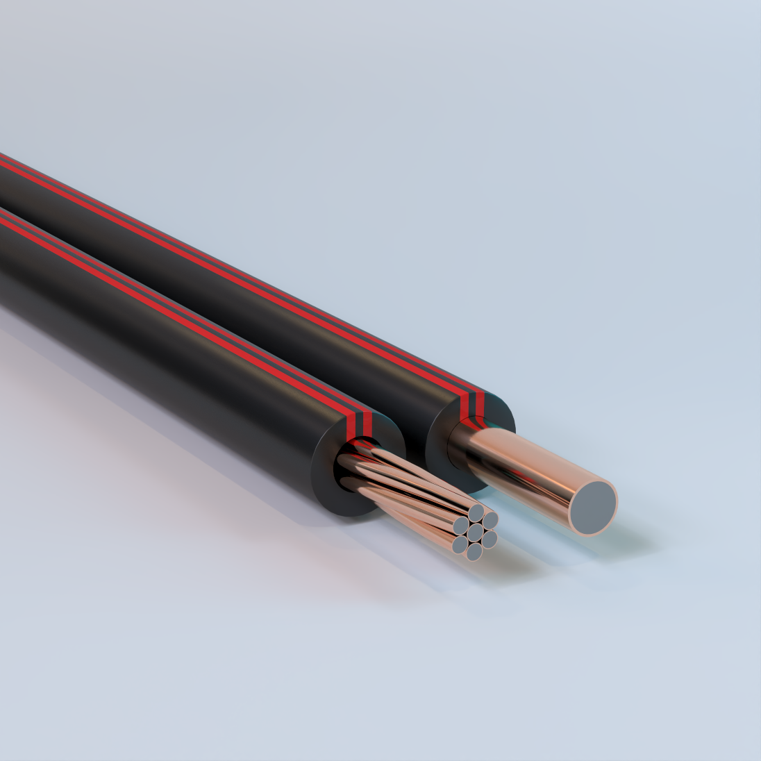
Copper-Clad Steel (CCS) Conductor High-Voltage Flexible Stinger Wire
Solid (Single End) or Concentric Lay Stranded, Grade 40 Drawn Steel Alloy (DSA) Core, Metallurgically Bonded Copper Cladding, 1 Solid or 7 Strand, Thermoplastic Elastomer (TPE) Insulation/Cover with UV Protection – Composite
Used as riser wire for cutouts and pole-top transformers, providing connections between primary phase conductors and equipment bushings, and for use as covered ground wire in distribution circuits. Available from Copperweld® under the Stingray™ product line.
Physical Data
| CCS Conductor – Stinger Wire – Single End or Concentric Lay Stranded | ||||||
|---|---|---|---|---|---|---|
| Construction | Number of Strands | Max. Ampacity* | Break Load | Overall Diameter | Insulation Thickness | Linear Weight |
| (amps) | (lbf) | (in) | (in) | (lb/ft) | ||
| #6 Cu-Clad Steel Equivalent |
1 | 90 | 1,035 | 0.382 | 0.11 | 0.112 |
| #6 Cu Equivalent | 7 | 135 | 1,115 | 0.412 | 0.11 | 0.126 |
| #4 Cu Equivalent | 7 | 195 | 2,013 | 0.558 | 0.15 | 0.232 |
| #2 Cu Equivalent | 7 | 245 | 2,826 | 0.606 | 0.15 | 0.3 |
| *The maximum rated ampacity listed is for short durations only. The recommended maximum continuous ampacity load is 65% of the rating shown. The above data are nominal values and are subject to normal manufacturing tolerances. Electrical performance values, including ampacity and short-circuit ratings, are based on standard test methods and calculation procedures and may vary depending on application and operating conditions. | ||||||

Bare Copper-Clad Steel (CCS) Conductor
Concentric Lay Stranded, Grade 40 Drawn Steel Alloy (DSA) Core, Metallurgically Bonded Copper Cladding, 61 Strand & 19 Strand – Composite
Used for substation grounding applications where grounding conductors must carry short-duration, high-magnitude current during fault or arc events without thermal or mechanical failure. Commonly specified for substation ground grids designed in accordance with IEEE Std 80, which establishes conductor sizing based on the ability to withstand high fault current for a defined duration. The higher strand count provides increased flexibility and mechanical strength compared to solid copper conductors, supporting efficient installation and optimized ground grid design. Available from Copperweld® under the ArcAngel™ product line.
Physical Data
| CCS Conductor – Concentric Lay Stranded | ||||||||
|---|---|---|---|---|---|---|---|---|
| Construction | Single End Diameter | Number of Strands | Integral Cross-Section | Overall Diameter | Linear Weight | Break Load | Resistance | Short Circuit Withstand Current |
| (in) | (kcmil) | (in) | (lbs/kft) | (lbf) | (Ω/kft) | (kA/0.5s) | ||
| #2 Cu Equivalent | 0.0700 | 19 | 93 | 0.35 | 264.7 | 3,619 | 0.294 | 14 |
| 0.0890 | 19 | 150 | 0.45 | 427.9 | 5,851 | 0.182 | 22 | |
| 2/0 Cu Equivalent | 0.0985 | 19 | 184 | 0.49 | 524.1 | 7,167 | 0.148 | 28 |
| 4/0 Cu Equivalent | 0.0689 | 61 | 290 | 0.62 | 828.2 | 11,258 | 0.095 | 44 |
| 250 kcmil Cu Equivalent | 0.0752 | 61 | 345 | 0.68 | 986.6 | 13,411 | 0.080 | 52 |
| 350 kcmil Cu Equivalent | 0.0890 | 61 | 483 | 0.80 | 1381.9 | 18,785 | 0.057 | 73 |
| 500 kcmil Cu Equivalent | 0.1045 | 61 | 667 | 0.94 | 1905.1 | 25,897 | 0.042 | 101 |
| The above data are nominal values and are subject to normal manufacturing tolerances. Electrical performance values, including ampacity and short-circuit ratings, are based on standard test methods and calculation procedures and may vary depending on application and operating conditions. | ||||||||
Bare Copper-Clad Steel (CCS) Conductor
Concentric Lay Stranded, Grade 40 Drawn Steel Alloy (DSA) Core, Metallurgically Bonded Copper Cladding, Tinned Finish, 19 Strand & 61 Strand including 1 Green Jacketed Indicator Strand – Composite
Used for substation grounding applications where grounding conductors must carry short-duration, high-magnitude current during fault or arc events without thermal or mechanical failure with an integrated indicator conductor for locating and identification. Commonly specified for substation ground grids designed in accordance with IEEE Std 80, which establishes conductor sizing based on the ability to withstand high fault current for a defined duration. The higher strand count provides increased flexibility and mechanical strength compared to solid copper conductors, supporting efficient installation and optimized ground grid design. Available from Copperweld® under the ArcAngel™ – Indicator product line.
Physical Data
| CCS Conductor – Concentric Lay Stranded with Green Indicator Wire | ||||||||
|---|---|---|---|---|---|---|---|---|
| Construction | Single End Diameter | Number of Strands | Integral Cross-Section | Overall Diameter | Linear Weight | Break Load | Resistance | Short Circuit Withstand Current |
| (in) | (kcmil) | (in) | (lbs/kft) | (lbf) | (Ω/kft) | (kA/0.5s) | ||
| #2 Cu Equivalent | 0.07 | 19 | 93 | 0.35 | 264.7 | 3,619 | 0.294 | 14 |
| 0.089 | 19 | 150 | 0.45 | 427.9 | 5,851 | 0.182 | 22 | |
| 2/0 Cu Equivalent | 0.0985 | 19 | 184 | 0.49 | 524.1 | 7,167 | 0.148 | 28 |
| 4/0 Cu Equivalent | 0.0689 | 61 | 290 | 0.62 | 828.2 | 11,258 | 0.095 | 44 |
| 250 kcmil Cu Equivalent | 0.0752 | 61 | 345 | 0.68 | 986.6 | 13,411 | 0.080 | 52 |
| 350 kcmil Cu Equivalent | 0.089 | 61 | 483 | 0.80 | 1381.9 | 18,785 | 0.057 | 73 |
| 500 kcmil Cu Equivalent | 0.1045 | 61 | 667 | 0.94 | 1905.1 | 25,897 | 0.042 | 101 |
| The above data are nominal values and are subject to normal manufacturing tolerances. Electrical performance values, including ampacity and short-circuit ratings, are based on standard test methods and calculation procedures and may vary depending on application and operating conditions. | ||||||||
Copper-Clad Aluminum (CCA) Conductor Photovoltaic (PV) Cable
Concentric Lay Stranded, AA 8000 Series Aluminum Core, Metallurgically Bonded Copper Cladding, Min. 10% Oxygen-Free Copper by Volume, XLPE Insulation, Direct Burial, 90° Wet or Dry, Sunlight Resistant, FV-1, Gasoline & Oil Resistant II, 2kV-Rated – Composite
Used as photovoltaic inter-panel, string, and homerun power conductors in solar power systems requiring voltage ratings up to 2,000V DC. Suitable for use in both grounded interconnection and ungrounded photovoltaic power systems, including PV source and output circuits exposed to outdoor environmental conditions Also available in red or white insulation/cover. Available from Copperweld® under the Sunray™ product line.
Physical Data
| CCA Conductor -Concentric Lay Stranded Photovoltaic (PV) Cable | ||||||
|---|---|---|---|---|---|---|
| AWG | Number of Strands | Insulation Thickness | Overall Diameter | Weight | Ampacity* | DC Resistance @ 20°C |
| (mils) | (in) | (lbs/kft) | (amps) | (Ω/kft) | ||
| #10 | 7 | 75 | 0.266 | 33.66 | 35 | 1.56 |
| #8 | 7 | 85 | 0.316 | 48.69 | 45 | 0.982 |
| #6 | 7 | 85 | 0.354 | 64.58 | 55 | 0.6176 |
| *The allowable ampacity of insulated conductor up to and including 2,000 volt, 90° C, not more than three current carrying conductors in a raceway, cable or earth, based on ambient temperature of 30° C. In 240.4 (D) article of NEC, it is established that the overcurrent protection shall not exceed 25 Amperes for 10 AWG. The above data are nominal values and are subject to normal manufacturing tolerances. Electrical performance values, including ampacity and short-circuit ratings, are based on standard test methods and calculation procedures and may vary depending on application and operating conditions. | ||||||
Bare Copper-Clad Aluminum (CCA) Conductor
Solid (Single End), AA 8000 Series Aluminum Core, Metallurgically Bonded Copper Cladding, 10% Oxygen-Free Copper by Volume, 38 AWG – 0 AWG – Composite
Used for grounding and utility applications. Commonly specified for grounding electrodes, counterpoise grounding systems, utility grounding and overhead static or shield wire applications where permitted by the National Electrical Code (NEC). Also may be available with a camoflauge (theft-deterrent) finish or PVC covering for select sizes.
Physical Data
| CCA Conductor – Single End | ||||||||
|---|---|---|---|---|---|---|---|---|
| AWG | Diameter | Cross-Sectional Area |
(cmil) | Nominal Copper Thickness (in) |
Weight (kg/km) |
Maximum DC Resistance (Ω/km) |
||
| (in) | in2 | CCA 10% | Copper | CCA 10% | Copper | |||
| 0 | 0.3249 | 0.082907 | 105,560 | 0.00812 | 119.4 | 319.6 | 0.159 | 0.104 |
| 1 | 0.2893 | 0.065733 | 83,694 | 0.00723 | 94.66 | 253.4 | 0.201 | 0.131 |
| 2 | 0.2576 | 0.052117 | 66,358 | 0.00644 | 75.05 | 200.9 | 0.254 | 0.166 |
| 3 | 0.2294 | 0.041331 | 52,624 | 0.00574 | 59.52 | 159.3 | 0.32 | 0.209 |
| 4 | 0.2043 | 0.032781 | 41,738 | 0.00511 | 47.21 | 126.4 | 0.403 | 0.264 |
| 5 | 0.1819 | 0.025987 | 33,088 | 0.00455 | 37.42 | 100.2 | 0.509 | 0.333 |
| 6 | 0.162 | 0.020612 | 26,244 | 0.00405 | 29.68 | 79.45 | 0.641 | 0.419 |
| 7 | 0.1443 | 0.016354 | 20,822 | 0.00361 | 23.55 | 63.03 | 0.809 | 0.528 |
| 8 | 0.1285 | 0.012969 | 16,512 | 0.00321 | 18.67 | 49.99 | 1.02 | 0.666 |
| 9 | 0.1144 | 0.010279 | 13,087 | 0.00286 | 14.8 | 39.62 | 1.286 | 0.841 |
| 10 | 0.1019 | 0.008155 | 10,384 | 0.00255 | 11.74 | 31.43 | 1.621 | 1.06 |
| 11 | 0.0907 | 0.006461 | 8,226 | 0.00227 | 9.304 | 24.9 | 2.046 | 1.338 |
| 12 | 0.0808 | 0.005128 | 6,529 | 0.00202 | 7.384 | 19.76 | 2.579 | 1.685 |
| 13 | 0.072 | 0.004072 | 5,184 | 0.0018 | 5.863 | 15.69 | 3.247 | 2.123 |
| 14 | 0.0641 | 0.003227 | 4,109 | 0.0016 | 4.647 | 12.44 | 4.097 | 2.678 |
| 15 | 0.0571 | 0.002561 | 3,260 | 0.00143 | 3.687 | 9.87 | 5.163 | 3.375 |
| 16 | 0.0508 | 0.002027 | 2,581 | 0.00127 | 2.919 | 7.812 | 6.524 | 4.264 |
| 17 | 0.0453 | 0.001612 | 2,052 | 0.00113 | 2.321 | 6.212 | 8.204 | 5.362 |
| 18 | 0.0403 | 0.001276 | 1,624 | 0.00101 | 1.837 | 4.917 | 10.37 | 6.775 |
| 19 | 0.0359 | 0.001012 | 1,289 | 0.0009 | 1.458 | 3.902 | 13.06 | 8.538 |
| 20 | 0.032 | 0.000804 | 1,024 | 0.0008 | 1.155 | 3.092 | 16.48 | 10.77 |
| 21 | 0.0285 | 0.000644 | 820 | 0.00072 | 0.928 | 2.483 | 20.52 | 13.41 |
| 22 | 0.0253 | 0.000505 | 642 | 0.00063 | 0.727 | 1.945 | 26.2 | 17.13 |
| 23 | 0.0226 | 0.0004 | 509 | 0.00056 | 0.576 | 1.542 | 33.04 | 21.6 |
| 24 | 0.0201 | 0.000317 | 404 | 0.0005 | 0.457 | 1.223 | 41.67 | 27.23 |
| 25 | 0.0179 | 0.000252 | 320 | 0.00045 | 0.362 | 0.97 | 52.54 | 34.34 |
| 26 | 0.0159 | 0.0002 | 254 | 0.0004 | 0.287 | 0.769 | 66.25 | 43.3 |
| 27 | 0.0142 | 0.000158 | 202 | 0.00035 | 0.228 | 0.61 | 83.54 | 54.6 |
| 28 | 0.0126 | 0.000126 | 160 | 0.00032 | 0.181 | 0.484 | 105.35 | 68.86 |
| 29 | 0.0113 | 0.0001 | 127 | 0.00028 | 0.143 | 0.384 | 132.8 | 86.82 |
| 30 | 0.01 | 7.9E-5 | 101 | 0.00025 | 0.114 | 0.304 | 167.5 | 109.5 |
| 31 | 0.0089 | 6.3E-5 | 80 | 0.00022 | 0.09 | 0.241 | 211.2 | 138.1 |
| 32 | 0.008 | 5.0E-5 | 63 | 0.0002 | 0.071 | 0.191 | 266.4 | 174.1 |
| 33 | 0.0071 | 3.9E-5 | 50 | 0.00018 | 0.057 | 0.152 | 335.9 | 219.5 |
| 34 | 0.0063 | 3.1E-5 | 40 | 0.00016 | 0.045 | 0.12 | 423.5 | 276.8 |
| 35 | 0.0056 | 2.5E-5 | 32 | 0.00014 | 0.036 | 0.095 | 534 | 349 |
| 36 | 0.005 | 2.0E-5 | 25 | 0.00013 | 0.028 | 0.076 | 673.4 | 440.2 |
| 37 | 0.0045 | 1.6E-5 | 20 | 0.00011 | 0.022 | 0.06 | 849 | 554.9 |
| 38 | 0.004 | 1.2E-5 | 16 | 0.0001 | 0.018 | 0.048 | 1,071 | 699.9 |
| The above data are approximate and subject to normal manufacturing tolerances. | ||||||||
Bare Copper-Clad Steel (CCS) Conductor Type M Guy Strands
Concentric Lay Stranded, Grade 40 Drawn Steel Alloy (DSA) Core, Metallurgically Bonded Copper Cladding, 7 Strand & 3 Strand – Composite
Used for guy wire (guy strand) and messenger wire (messenger strand) applications in utility, communications, and infrastructure installations where mechanical strength, corrosion resistance, and long service life are required. Suitable for applications requiring electrical continuity, bonding, or grounding compatibility where permitted by applicable codes and standards. Available from Copperweld®.
Physical Data
| Bare Copper-Clad Steel (CCS) Conductor Type M Guy Strands | ||||
|---|---|---|---|---|
| Designation | Nom. Diameter of Strand |
Number and Diameter of Individual Wires |
Rated Strength |
Weight |
| (in) | ( in) | (lbs) | (lbs/kft) | |
| 2.2M | 0.164 | 3 x 0.076 | 2,200 | 49 |
| 4M | 0.209 | 3 x 0.097 | 4,000 | 79 |
| 6M3 | 0.258 | 3 x 0.120 | 6,000 | 121 |
| 6M | 0.237 | 7 x 0.076 | 6000 | 122 |
| 8M | 0.276 | 7 x 0.092 | 8,000 | 166 |
| 10M | 0.303 | 7 x 0.101 | 10,000 | 200 |
| 12.5M | 0.345 | 7 x 0.115 | 12,500 | 259 |
| 14M | 0.36 | 7 x 0.120 | 14,000 | 283 |
| 16M | 0.386 | 7 x 0.128 | 16,000 | 324 |
| 18M | 0.414 | 7 x .0138 | 18,000 | 374 |
| 20M | 0.438 | 7 x 0.146 | 20,000 | 418 |
| The above data are approximate and subject to normal manufacturing tolerances. | ||||
Bare Copper-Clad Steel (CCS)/Bare Copper (Cu) Composite Concentric Lay Stranded Conducters
Grade 40 Steel Core with Metallurgically Bonded Copper Cladding Conductor & Bare Copper Conductor – Composite
Used in overhead transmission and distribution systems where predictable electrical performance is required. These composite stranded conductors are applied in line and grounding configurations to evaluate resistance, inductive and capacitive reactance, geometric mean radius, and ampacity at 60 hertz. Commonly referenced for conductor selection, system modeling, and spacing analysis in utility and infrastructure applications. Available from Copperweld®.
Electrical Data
| CCS/Bare Copper Composite Concentric Lay Stranded Conductors | ||||||||
|---|---|---|---|---|---|---|---|---|
| Conductor | Resistance-Ohms per Conductor per Mile* | Reactance per Conductor per Mile (One Foot Spacing) |
Geometric Mean Radius at 60 Hz |
Approx. Ampacity** at 60 Hz |
||||
| r_{a} at 25°C (77°F) Small Currents |
r_{a} at 50°C (122°F) Current-Approx. 75% of Ampacity |
x_{a} Inductive (Ω at 60 Hz) |
x’a Capacitive (Ω at 60 Hz) |
(Feet) | (Amps) | |||
| D.C. | 60 Hz | D.C. | 60 Hz | |||||
| 350 E | 0.1658 | 0.1812 | 0.1812 | 0.204 | 0.463 | 0.1014 | 0.022 | 660 |
| 350 EK | 0.1658 | 0.1705 | 0.1812 | 0.1882 | 0.45 | 0.1034 | 0.0245 | 680 |
| 300 E | 0.1934 | 0.209 | 0.211 | 0.235 | 0.473 | 0.1037 | 0.0204 | 600 |
| 300 EK | 0.1934 | 0.1981 | 0.211 | 0.219 | 0.46 | 0.1057 | 0.0227 | 610 |
| 250 E | 0.232 | 0.248 | 0.254 | 0.279 | 0.484 | 0.1064 | 0.01859 | 540 |
| 250 EK | 0.232 | 0.237 | 0.254 | 0.261 | 0.471 | 0.1084 | 0.0207 | 540 |
| 4/0 E | 0.274 | 0.29 | 0.3 | 0.326 | 0.493 | 0.1088 | 0.01711 | 480 |
| 4/0 G | 0.273 | 0.298 | 0.299 | 0.342 | 0.517 | 0.1103 | 0.01409 | 460 |
| 4/0 EK | 0.274 | 0.279 | 0.3 | 0.308 | 0.481 | 0.1109 | 0.01903 | 490 |
| 4/0 F | 0.273 | 0.287 | 0.299 | 0.322 | 0.505 | 0.112 | 0.01558 | 470 |
| 3/0E | 0.346 | 0.361 | 0.378 | 0.407 | 0.508 | 0.1123 | 0.01521 | 420 |
| 3/0 J | 0.344 | 0.372 | 0.377 | 0.428 | 0.541 | 0.1118 | 0.01156 | 410 |
| 3/0 G | 0.344 | 0.369 | 0.377 | 0.423 | 0.531 | 0.1137 | 0.01254 | 400 |
| 3/0 EK | 0.346 | 0.351 | 0.378 | 0.386 | 0.495 | 0.1143 | 0.01697 | 420 |
| 3/0 F | 0.344 | 0.358 | 0.377 | 0.401 | 0.519 | 0.1155 | 0.01388 | 410 |
| 2/0 K | 0.434 | 0.466 | 0.475 | 0.535 | 0.57 | 0.1129 | 0.00912 | 360 |
| 2/0 J | 0.434 | 0.462 | 0.475 | 0.53 | 0.555 | 0.1152 | 0.01029 | 350 |
| 2/0 G | 0.434 | 0.459 | 0.475 | 0.525 | 0.545 | 0.1171 | 0.01119 | 350 |
| 2/0 F | 0.434 | 0.448 | 0.475 | 0.501 | 0.533 | 0.1189 | 0.01235 | 350 |
| 1/0 K | 0.548 | 0.579 | 0.599 | 0.664 | 0.584 | 0.1164 | 0.00812 | 310 |
| 1/0 J | 0.548 | 0.576 | 0.599 | 0.659 | 0.569 | 0.1186 | 0.00917 | 310 |
| 1/0 G | 0.548 | 0.573 | 0.599 | 0.654 | 0.559 | 0.1206 | 0.00996 | 310 |
| 1/0 F | 0.548 | 0.562 | 0.599 | 0.627 | 0.547 | 0.1224 | 0.01099 | 310 |
| 1 N | 0.691 | 0.726 | 0.755 | 0.832 | 0.614 | 0.1171 | 0.00638 | 280 |
| 1 K | 0.691 | 0.722 | 0.755 | 0.825 | 0.598 | 0.1198 | 0.00723 | 270 |
| 1 J | 0.691 | 0.719 | 0.755 | 0.82 | 0.583 | 0.1221 | 0.00817 | 270 |
| 1 G | 0.691 | 0.716 | 0.755 | 0.815 | 0.573 | 0.124 | 0.00887 | 260 |
| 1 F | 0.691 | 0.705 | 0.755 | 0.786 | 0.561 | 0.1258 | 0.0098 | 270 |
| 2P | 0.871 | 0.909 | 0.952 | 1.04 | 0.643 | 0.1172 | 0.00501 | 250 |
| 2N | 0.871 | 0.906 | 0.952 | 1.035 | 0.627 | 0.1205 | 0.00568 | 240 |
| 2K | 0.871 | 0.902 | 0.952 | 1.028 | 0.612 | 0.1232 | 0.00644 | 240 |
| 2J | 0.871 | 0.899 | 0.952 | 1.022 | 0.598 | 0.1255 | 0.00727 | 230 |
| 2A | 0.869 | 0.882 | 0.95 | 0.979 | 0.592 | 0.1241 | 0.00763 | 240 |
| 2G | 0.871 | 0.896 | 0.952 | 1.016 | 0.587 | 0.1275 | 0.0079 | 230 |
| 2F | 0.871 | 0.885 | 0.952 | 0.985 | 0.575 | 0.1292 | 0.00873 | 230 |
| 3P | 1.098 | 1.136 | 1.2 | 1.296 | 0.657 | 0.1207 | 0.00445 | 220 |
| 3N | 1.098 | 1.133 | 1.2 | 1.289 | 0.641 | 0.1239 | 0.00506 | 210 |
| 3K | 1.098 | 1.129 | 1.2 | 1.281 | 0.626 | 0.1266 | 0.00574 | 210 |
| 3J | 1.098 | 1.126 | 1.2 | 1.275 | 0.611 | 0.1289 | 0.00648 | 200 |
| 3A | 1.096 | 1.109 | 1.198 | 1.229 | 0.606 | 0.1275 | 0.00679 | 210 |
| 4P | 1.385 | 1.423 | 1.514 | 1.616 | 0.671 | 0.1241 | 0.00397 | 190 |
| 4N | 1.385 | 1.42 | 1.514 | 1.61 | 0.655 | 0.1274 | 0.00451 | 180 |
| 4D | 1.382 | 1.399 | 1.511 | 1.542 | 0.628 | 0.1256 | 0.00566 | 190 |
| 4A | 1.382 | 1.395 | 1.511 | 1.545 | 0.62 | 0.131 | 0.00604 | 180 |
| 5P | 1.747 | 1.785 | 1.909 | 2.02 | 0.685 | 0.1275 | 0.00353 | 160 |
| 5D | 1.742 | 1.759 | 1.905 | 1.939 | 0.642 | 0.129 | 0.00504 | 160 |
| 5A | 1.742 | 1.755 | 1.905 | 1.941 | 0.634 | 0.1345 | 0.00538 | 160 |
| 6D | 2.2 | 2.22 | 2.4 | 2.44 | 0.656 | 0.1325 | 0.00449 | 140 |
| 6A | 0.871 | 0.909 | 0.952 | 1.04 | 0.643 | 0.1172 | 0.00501 | 250 |
| 6C | 0.871 | 0.906 | 0.952 | 1.035 | 0.627 | 0.1205 | 0.00568 | 240 |
| 7D | 0.871 | 0.902 | 0.952 | 1.028 | 0.612 | 0.1232 | 0.00644 | 240 |
| 7A | 0.871 | 0.899 | 0.952 | 1.022 | 0.598 | 0.1255 | 0.00727 | 230 |
| 8D | 0.869 | 0.882 | 0.95 | 0.979 | 0.592 | 0.1241 | 0.00763 | 240 |
| 8A | 0.871 | 0.896 | 0.952 | 1.017 | 0.587 | 0.1275 | 0.0079 | 230 |
| 8C | 0.871 | 0.885 | 0.952 | 0.985 | 0.575 | 0.1292 | 0.00873 | 230 |
| 9½D | 1.098 | 1.136 | 1.2 | 1.296 | 0.657 | 0.1207 | 0.00445 | 220 |
| *Resistance at 75ºC total temperature, based on ambient of 25ºC plus 50ºC rise due to heating effect of current. The approximate magnitude of current necessary to produce the 50ºC rise is 75% of the “Approximate Ampacity at 60 Hertz.” **Based on a conductor temperature of 125ºC and an ambient of 25ºC. A 2 ft/s wind speed and Emissivity = 0.5. The above data are nominal values and are subject to normal manufacturing tolerances. Electrical performance values, including ampacity and short-circuit ratings, are based on standard test methods and calculation procedures and may vary depending on application and operating conditions. | ||||||||
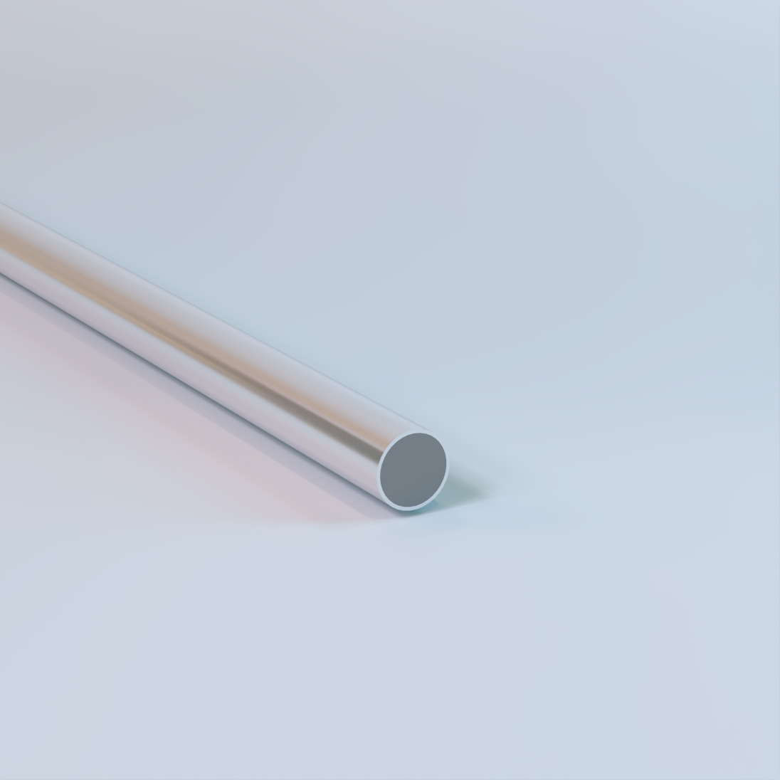
Bare Aluminum-Clad Steel (ACS) Conductor
Solid (Single End), Hard-Drawn Round Steel Core with Bonded Extruded Aluminum Cladding – Composite
Used for transmission and utility applications including overhead shield wire (static wire) and overhead ground wire installations. Provides lightning protection and grounding performance in transmission and distribution systems. Commonly specified for installations in high-corrosion environments including industrial, coastal, and desert regions. Also suitable for grounding systems, counterpoise applications, and formed wire applications such as dead-ends and related hardware assemblies. Availability of size, conductivity class, and mechanical strength varies by specification.
Physical Data
| ACS Single End | |||||||||||||
|---|---|---|---|---|---|---|---|---|---|---|---|---|---|
| Size/AWG | Diameter | Ultimate Tensile Strength |
Minimum Breaking Strength |
Weight | Resistance at 20° | C mils | Cross Section | ||||||
| inches | mm | ksi | kg/mm2 | lbs. | kg | lbs./1,000 ft. |
kg/km | Ω/1,000 ft. |
Ω/km | inches2 | mm2 | ||
| 4 | 0.2043 | 5.189 | 155 | 109 | 5,081 | 2,304.6 | 93.63 | 139.34 | 1.222 | 4.01 | 41,740 | 0.033 | 21.15 |
| 0.188 | 4.775 | 160 | 112.5 | 4,441 | 2,014.6 | 79.29 | 118 | 1.443 | 4.735 | 35,340 | 0.028 | 17.91 | |
| 5 | 0.1819 | 4.62 | 165 | 116 | 4,290 | 1,945.9 | 74.25 | 110.5 | 1.541 | 5.056 | 33,090 | 0.026 | 16.77 |
| 0.1729 | 4.392 | 170 | 119.5 | 3,991 | 1,810.4 | 67.09 | 99.84 | 1.706 | 5.598 | 29,900 | 0.023 | 15.15 | |
| 6 | 0.162 | 4.114 | 175 | 123 | 3,608 | 1,636.6 | 58.88 | 87.62 | 1.943 | 6.375 | 26,240 | 0.021 | 13.3 |
| 0.1549 | 3.934 | 180 | 126.6 | 3,392 | 1,538.8 | 53.84 | 80.13 | 2.126 | 6.974 | 24,000 | 0.019 | 12.16 | |
| 7 | 0.1443 | 3.665 | 185 | 130.1 | 3,025 | 1,372.1 | 46.69 | 69.48 | 2.45 | 8.038 | 20,820 | 0.016 | 10.55 |
| 0.1369 | 3.477 | 190 | 133.6 | 2,796 | 1,268.5 | 42.04 | 62.57 | 2.722 | 8.931 | 18,740 | 0.015 | 9.495 | |
| 8 | 0.1285 | 3.264 | 195 | 137.1 | 2,529 | 1,147.1 | 37.03 | 55.11 | 3.089 | 10.135 | 16,510 | 0.013 | 8.367 |
| 9 | 0.1144 | 2.906 | 195 | 137.1 | 2,005 | 909.4 | 29.37 | 43.71 | 3.896 | 12.783 | 13,090 | 0.01 | 6.632 |
| 10 | 0.1019 | 2.588 | 195 | 137.1 | 1,590 | 721.2 | 23.29 | 34.66 | 4.912 | 16.116 | 10,380 | 0.008 | 5.261 |
| 11 | 0.0907 | 2.304 | 195 | 137.1 | 1,269 | 571.9 | 18.47 | 27.49 | 6.194 | 20.322 | 8,230 | 0.006 | 4.168 |
| 12 | 0.0808 | 2.052 | 195 | 137.1 | 1,000 | 453.6 | 14.65 | 21.8 | 7.811 | 25.627 | 6,530 | 0.005 | 3.31 |
| The above data are approximate and subject to normal manufacturing tolerances. | |||||||||||||
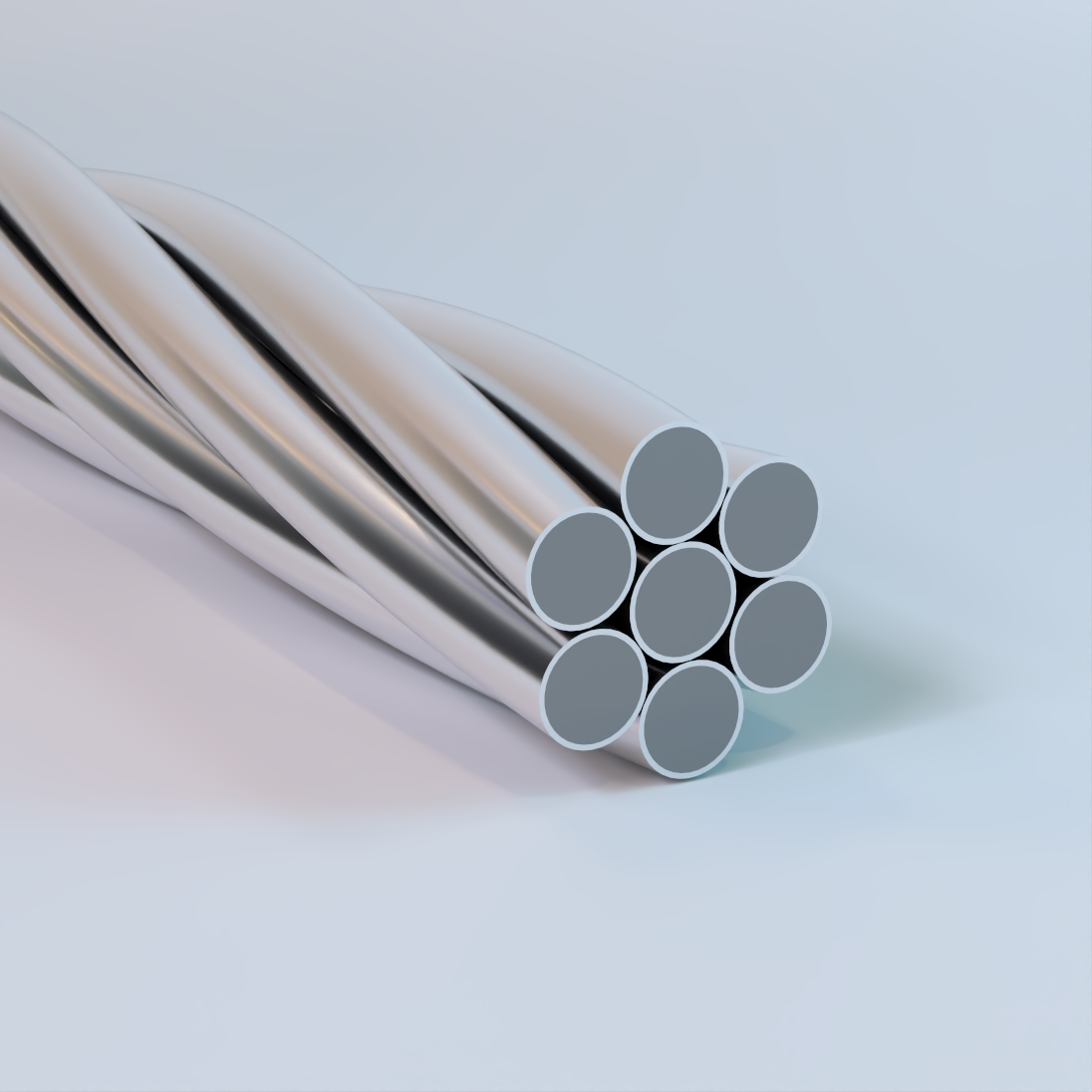
Aluminum-Clad Steel (ACS) Shield Wire
Bare Overhead Concentric Lay Stranded, Hard-Drawn Round Steel Core with Bonded Extruded Aluminum Cladding – Composite
Used for transmission and utility applications including overhead shield wire (static wire) and overhead ground wire installations. Provides lightning protection and distributed grounding critical to the safe operation of transmission and distribution systems. Commonly specified for use in high-corrosion environments including industrial, coastal, and desert regions. Availability of strand construction, size, and mechanical strength varies by specification.
Physical Data
| ACS Shield Wire | |||||||
|---|---|---|---|---|---|---|---|
| Size Nos/AWG | Individual Wire Diameter (in.) |
Stranded Diameter (in.) |
Breaking Load (lb.) |
Weight (lb./1000 ft.) |
Resistance at 20°C (Ω/1000 ft.) |
(C mils.) | Cross Section |
| (in²) | |||||||
| 37/5 | 0.1819 | 1.27 | 142,800 | 2,802 | 0.04247 | 1,225,000 | 0.9619 |
| 37/6 | 0.162 | 1.13 | 120,200 | 2,222 | 0.05356 | 971,300 | 0.7629 |
| 37/7 | 0.1443 | 1.01 | 100,700 | 1,762 | 0.06754 | 770,300 | 0.605 |
| 37/8 | 0.1285 | 0.899 | 84,200 | 1,398 | 0.08516 | 610,900 | 0.4798 |
| 37/9 | 0.1144 | 0.801 | 66,700 | 1,108 | 0.1074 | 484,400 | 0.3805 |
| 37/10 | 0.1019 | 0.713 | 52,950 | 879 | 0.1354 | 384,200 | 0.3017 |
| 19/5 | 0.1819 | 0.91 | 73,350 | 1,430 | 0.08224 | 628,900 | 0.494 |
| 19/6 | 0.162 | 0.81 | 61,700 | 1,134 | 0.1037 | 498,800 | 0.3917 |
| 19/7 | 0.1443 | 0.721 | 51,730 | 889.5 | 0.1308 | 395,500 | 0.3107 |
| 19/8 | 0.1285 | 0.642 | 43,240 | 713.5 | 0.1649 | 313,700 | 0.2464 |
| 19/9 | 0.1144 | 0.572 | 34,290 | 565.8 | 0.2079 | 248,800 | 0.1954 |
| 19/10 | 0.1019 | 0.509 | 27,190 | 448.7 | 0.2622 | 197,300 | 0.1549 |
| 7/5 | 0.1819 | 0.546 | 27,030 | 524.9 | 0.2264 | 231,700 | 0.182 |
| 7/6 | 0.162 | 0.486 | 22,730 | 416.3 | 0.2803 | 183,800 | 0.1443 |
| 7/7 | 0.1443 | 0.433 | 19,060 | 330 | 0.3535 | 145,700 | 0.1145 |
| 7/8 | 0.1285 | 0.385 | 15,930 | 261.8 | 0.4458 | 115,600 | 0.09077 |
| 7/9 | 0.1144 | 0.343 | 12,630 | 207.6 | 0.5621 | 91,650 | 0.07198 |
| 7/10 | 0.1019 | 0.306 | 10,020 | 164.7 | 0.7088 | 72,680 | 0.05708 |
| 7/11 | 0.0907 | 0.272 | 7,945 | 130.6 | 0.8938 | 57,590 | 0.04523 |
| 7/12 | 0.0808 | 0.242 | 6,301 | 103.6 | 1.127 | 45,710 | 0.0359 |
| 3/5 | 0.1819 | 0.392 | 12,230 | 224.5 | 0.5177 | 99,310 | 0.078 |
| 3/6 | 0.162 | 0.349 | 10,280 | 178.1 | 0.6528 | 78,750 | 0.06185 |
| 3/7 | 0.1443 | 0.311 | 8,621 | 141.2 | 0.8232 | 62,450 | 0.04905 |
| 3/8 | 0.1285 | 0.277 | 7,206 | 112 | 1.038 | 49,530 | 0.0389 |
| 3/9 | 0.1144 | 0.247 | 5,715 | 88.81 | 1.309 | 39,280 | 0.03085 |
| 3/10 | 0.1019 | 0.22 | 4,532 | 70.43 | 1.651 | 31,150 | 0.02446 |
| The above data are approximate and subject to normal manufacturing tolerances. | |||||||

Aluminum-Clad Steel (ACS) Guy & Messenger Wire
Bare Overhead Concentric Lay Stranded, Hard-Drawn Round Steel Core with Bonded Extruded Aluminum Cladding – Composite
Used for transmission and utility structural support applications including guy strand and messenger wire installations. Designed to provide high tensile strength and mechanical reinforcement for pole stabilization and aerial cable support systems. Commonly specified for use in high-corrosion environments including industrial, coastal, and desert regions. Availability of strand construction, size, and mechanical strength varies by specification.
Physical Data
| ACS Guy & Messenger Wire | ||||||
|---|---|---|---|---|---|---|
| Designation | Construction Nos. (in.) | AWG (equiv.) | Stranded Diameter (in.) | Cross Section (in²) | Breaking Load (lb.) | Weight lb./1000 ft. |
| 4 MG3 | 3/0.102 | 3/10 | 0.220 | 0.0245 | 4,500 | 70.61 |
| 5 MG3 | 3/0.114 | 3/9 | 0.247 | 0.0306 | 5,600 | 88.18 |
| 6 MG | 7/0.081 | 7/12 | 0.242 | 0.0361 | 6,300 | 104.1 |
| 6.6 MG | 7/0.083 | 0.249 | 0.0379 | 6,600 | 109.3 | |
| 7 MG3 | 3/0.128 | 3/8 | 0.277 | 0.0386 | 7,100 | 111.2 |
| 8 MG | 7/0.091 | 7/11 | 0.272 | 0.0455 | 8,000 | 131.4 |
| 5/16 IN. MG3 | 3/0.141 | 3/7 | 5/16 | 0.0495 | 8,400 | 142.7 |
| 10 MG | 7/0.102 | 7/10 | 0.306 | 0.0572 | 10,000 | 165.1 |
| 5/16 IN. MG | 7/0.104 | 5/16 | 0.0595 | 10,400 | 171.6 | |
| 11.5 MG | 7/0.110 | 0.330 | 0.0665 | 11,600 | 192.0 | |
| 12.5 MG | 7/0.114 | 7/9 | 0.343 | 0.0714 | 12,500 | 206.2 |
| 3/8 IN. MG | 7/0.121 | 0.0792 | 13,800 | 228.4 | ||
| 14 MG | 7/0.121 | 0.363 | 0.0805 | 14,100 | 232.2 | |
| 16 MG | 7/0.128 | 7/8 | 0.386 | 0.0901 | 16,000 | 260.0 |
| 18 MG | 7/0.139 | 0.417 | 0.1062 | 18,000 | 306.6 | |
| 7/16 IN. MG | 7/0.145 | 7/7 | 7/16 | 0.1156 | 18,700 | 333.6 |
| 20 MG | 7/0.148 | 0.444 | 0.1204 | 20,000 | 347.5 | |
| 1/2 IN. MG | 7/0.165 | 1/2 | 0.1497 | 22,900 | 432.0 | |
| 25 MG | 7/0.173 | 0.519 | 0.1645 | 25,000 | 474.8 | |
| The above data are approximate and subject to normal manufacturing tolerances. | ||||||
AWAC (AS/AC)
Aluminum Conductor, Aluminum-Clad Steel Reinforced, Bare Overhead Concentric Lay Stranded Conductors – Composite
Used for transmission and utility applications including overhead phase conductors where increased span length and mechanical strength are required. Commonly specified to improve conductor clearances and structural performance in transmission and distribution systems. Also utilized as neutral messengers for spacer cable systems and in certain ground or shield wire and self-supporting cable applications. Availability of strand construction, size, and mechanical strength varies by specification.
Physical Data
| AWAC (AS/AC) Wire | |||||||
|---|---|---|---|---|---|---|---|
No. 4 Awg Aluminum Equivalent |
|||||||
| No. 4-6/1 | 0.245 | 6- .0187 | 1- .0817 | 1783 | 52.4 | 276.7 | 0.0367 |
| No. 4-5/2 | 0.261 | 5- .0871 | 2- .0817 | 2830 | 69.7 | 368 | 0.0417 |
| No. 4-4/3 | 0.281 | 4- .0937 | 3- .0937 | 4305 | 92.4 | 487.9 | 0.0438 |
| No. 4-3/4 | 0.307 | 3- .1022 | 4- .1022 | 6325 | 123.7 | 652.1 | 0.0574 |
| No. 4-2/5 | 0.34 | 2- .1133 | 5- .1133 | 9314 | 169.4 | 894.4 | 0.0706 |
No. 3 Awg Aluminum Equivalent |
|||||||
| No. 3-6/1 | 0.275 | 6- .0918 | 1- .0918 | 2228 | 66.1 | 349 | 0.0463 |
| No. 3-5/2 | 0.293 | 5- .0978 | 2- .0978 | 3551 | 87.8 | 463.7 | 0.0526 |
| No. 3-4/3 | 0.316 | 4- .1053 | 3- .1053 | 5397 | 116.5 | 615.1 | 0.0609 |
| No. 3-3/4 | 0.344 | 3- .1147 | 4- .1147 | 7966 | 155.9 | 823.2 | 0.0723 |
| No. 3-2/5 | 0.382 | 2- .1273 | 5- .1273 | 11730 | 213.5 | 1127 | 0.089 |
No. 2 Awg Aluminum Equivalent |
|||||||
| No. 2-6/1 | 0.309 | 6- .1030 | 1- .1030 | 2760 | 83.3 | 439.8 | 0.0584 |
| No. 2-5/2 | 0.33 | 5- .1099 | 2- .1099 | 4336 | 110.8 | 585 | 0.0663 |
| No. 2-4/3 | 0.355 | 4- .1182 | 3- .1182 | 6785 | 146.9 | 775.6 | 0.0768 |
| No. 2-3/4 | 0.386 | 3- .1288 | 4- .1288 | 9793 | 196.6 | 1038 | 0.0912 |
| No. 2-2/5 | 0.429 | 2- .1429 | 5- .1429 | 14060 | 269.3 | 1422 | 0.1123 |
No. 1 Awg Aluminum Equivalent |
|||||||
| No. 1-6/1 | 0.347 | 6- .1157 | 1- .1157 | 3450 | 105.1 | 554.9 | 0.0736 |
| No. 1-5/2 | 0.37 | 5- .1234 | 2- .1234 | 5539 | 139.7 | 737.6 | 0.0837 |
| No. 1-4/3 | 0.398 | 4- .1327 | 3- .1327 | 8344 | 185.3 | 978.4 | 0.0969 |
| No. 1-3/4 | 0.434 | 3- .1446 | 4- .1446 | 11740 | 247.9 | 1309 | 0.115 |
| No. 1-2/5 | 0.482 | 2- .1605 | 5- .1605 | 16800 | 339.6 | 1793 | 0.1416 |
No. 1/0 Awg Aluminum Equivalent |
|||||||
| No. 1/0-6/1 | 0.39 | 6- .1300 | 1- .1300 | 4246 | 132.6 | 700.1 | 0.0929 |
| No. 1/0-5/2 | 0.416 | 5- .1385 | 2- .1385 | 6712 | 176.1 | 929.8 | 0.1055 |
| No. 1/0-4/3 | 0.447 | 4- .1490 | 3- .1490 | 10020 | 233.5 | 1233 | 0.1221 |
| No. 1/0-3/4 | 0.487 | 3- .1624 | 4- .1624 | 14000 | 312.6 | 1651 | 0.145 |
| No. 1/0-2/5 | 0.541 | 2- .1802 | 5- .1802 | 20030 | 428 | 2260 | 0.1785 |
No. 2/0 Awg Aluminum Equivalent |
|||||||
| No. 2/0-6/1 | 0.438 | 6- .1459 | 1- .1459 | 5135 | 167.1 | 882.3 | 0.1171 |
| No. 2/0-5/2 | 0.467 | 5- .1556 | 2- .1556 | 8040 | 221.1 | 1173 | 0.133 |
| No. 2/0-4/3 | 0.502 | 4- .1674 | 3- .1674 | 12000 | 294.6 | 1555 | 0.1541 |
| No. 2/0-3/4 | 0.547 | 3- .1824 | 4- .1824 | 16750 | 394.3 | 2082 | 0.1829 |
No. 3/0 Awg Aluminum Equivalent |
|||||||
| No. 3/0-6/1 | 0.492 | 6- .1639 | 1- .1639 | 6305 | 210.7 | 1112 | 0.1476 |
| No. 3/0-5/2 | 0.524 | 5- .1747 | 2- .1747 | 9705 | 280.6 | 1482 | 0.1677 |
| No. 3/0-4/3 | 0.564 | 4- .1880 | 3- .1880 | 14380 | 371.4 | 1961 | 0.1942 |
No. 4/0 Awg Aluminum Equivalent |
|||||||
| No. 4/0-6/1 | 0.552 | 6- .1840 | 1- .1840 | 7685 | 265.7 | 1403 | 0.1861 |
| No. 4/0-15/4 | 0.575 | 15- .1150 | 4- .1150 | 10870 | 305.4 | 1613 | 0.1974 |
| The above data are approximate and subject to normal manufacturing tolerances. | |||||||
Utility Steel Strand
Guy, Static & Messenger Wire, Galvanized or Zinc-5% Aluminum Alloy Coated, 3 Strand, 7 Strand & 19 Strand – Steel
Commonly referred to as galvanized guy wire, it’s used for structural support and stabilization in electric utility and communications infrastructure including, pole guying, overhead static and ground wire applications, and messenger cable support. It provides high tensile strength and long-term corrosion resistance in outdoor environments. Galvanized (zinc-coated) strand is for reliable performance in standard utility installations, while zinc-5% aluminum alloy coated strand offers enhanced corrosion protection for coastal, industrial, and extended design-life applications. Designed to anchor and stabilize poles and towers, support aerial cable systems, and provide dependable grounding continuity where uninterrupted mechanical and electrical performance is required. Stocked primarily in extra high strength (EHS) grade. Other grades available upon request.
Physical Data
| Utility Steel Strand | |||||||||||
|---|---|---|---|---|---|---|---|---|---|---|---|
| Galvanized Steel Strand | Minimum Breaking Strength (lbs) | Minimum Weight of Coating (oz./sq.ft.) | |||||||||
| Strand Diameter (in) | Coated Diameter(in) | Wires Per Strand | Strand Weight (lb/kft) | Utilities Grade | Common Grade | Siemens-Martin® Grade | High Strength Grade | Extra High Strength Grade | Class A | Class B | Class C |
| 1/4 | .120 | 3 | 117 | 3150 | 1860 | 3040 | 4730 | 6740 | .85 | 1.70 | 2.55 |
| 1/4 | .120 | 3 | 117 | 4500 | .85 | 1.70 | 2.55 | ||||
| 5/16 | .145 | 3 | 171 | 6500 | 2490 | 4090 | 6350 | 9100 | .90 | 1.80 | 2.70 |
| 3/8 | .165 | 3 | 220 | 8500 | 3330 | 5560 | 8360 | 11800 | .90 | 1.80 | 2.70 |
| 3/16 | .062 | 7 | 73 | 1150 | 1900 | 2850 | 3990 | .5 | 1.0 | 1.5 | |
| 3/16 | .065 | 7 | 801 | 2400 | .5 | 1.0 | 1.5 | ||||
| 7/32 | .072 | 7 | 98 | 1540 | 2560 | 3850 | 5400 | .5 | 1.0 | 1.5 | |
| 1/4 | .080 | 7 | 121 | 1900 | 3150 | 4750 | 6650 | .6 | 1.2 | 1.8 | |
| 9/32 | .093 | 7 | 164 | 4600 | 2570 | 4250 | 6400 | 8950 | .7 | 1.4 | 2.1 |
| 5/16 | .104 | 7 | 205 | 3200 | 5350 | 8000 | 11200 | .8 | 1.6 | 2.4 | |
| 5/16 | .109 | 7 | 225 | 6000 | .8 | 1.6 | 2.4 | ||||
| 3/8 | .120 | 7 | 273 | 11500 | 4250 | 6950 | 10800 | 15400 | .85 | 1.7 | 2.55 |
| 7/16 | .145 | 7 | 399 | 18000 | 5700 | 9350 | 14500 | 20800 | .9 | 1.8 | 2.7 |
| 1/2 | .165 | 7 | 517 | 2500 | 7400 | 12100 | 18800 | 26900 | .9 | 1.8 | 2.7 |
| 9/16 | .188 | 7 | 671 | 9600 | 15700 | 24500 | 35000 | 1.0 | 2.0 | 3.0 | |
| 5/8 | .207 | 7 | 813 | 11600 | 19100 | 29600 | 42400 | 1.0 | 2.0 | 3.0 | |
| 1/2 | .100 | 19 | 504 | 7620 | 12700 | 19100 | 26700 | .7 | 1.4 | 2.1 | |
| 9/16 | .113 | 19 | 637 | 9640 | 16100 | 24100 | 33700 | .8 | 1.6 | 2.4 | |
| 5/8 | .125 | 19 | 796 | 11000 | 18100 | 28100 | 40200 | .85 | 1.7 | 2.55 | |
| 3/4 | .150 | 19 | 1155 | 16000 | 26200 | 40800 | 58300 | .9 | 1.8 | 2.7 | |
| 7/8 | .177 | 19 | 1581 | 21900 | 35900 | 55800 | 79700 | .9 | 1.8 | 2.7 | |
| 1 | .200 | 19 | 2073 | 28700 | 47000 | 73200 | 104500 | 1.0 | 2.0 | 3.0 | |
| The above data are approximate and subject to normal manufacturing tolerances. | |||||||||||