Transmission & Distribution Cable
Aluminum Conductor
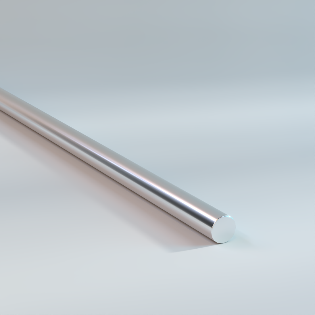
Tie Wire
Used for attaching cables to pin-type insulators, and for binding armor rods to the conductor.
Physical Data
| Tie Wire | |||
|---|---|---|---|
| Size | Diameter | Weight | Breaking Strength |
| AWG | in | lb/kft | lb |
| 6 | .1620 | 24.12 | 232 |
| 4 | .2043 | 38.35 | 369 |
| 2 | .2576 | 60.98 | 586 |
| The above data are approximate and subject to normal manufacturing tolerances. Other sizes available upon request. | |||

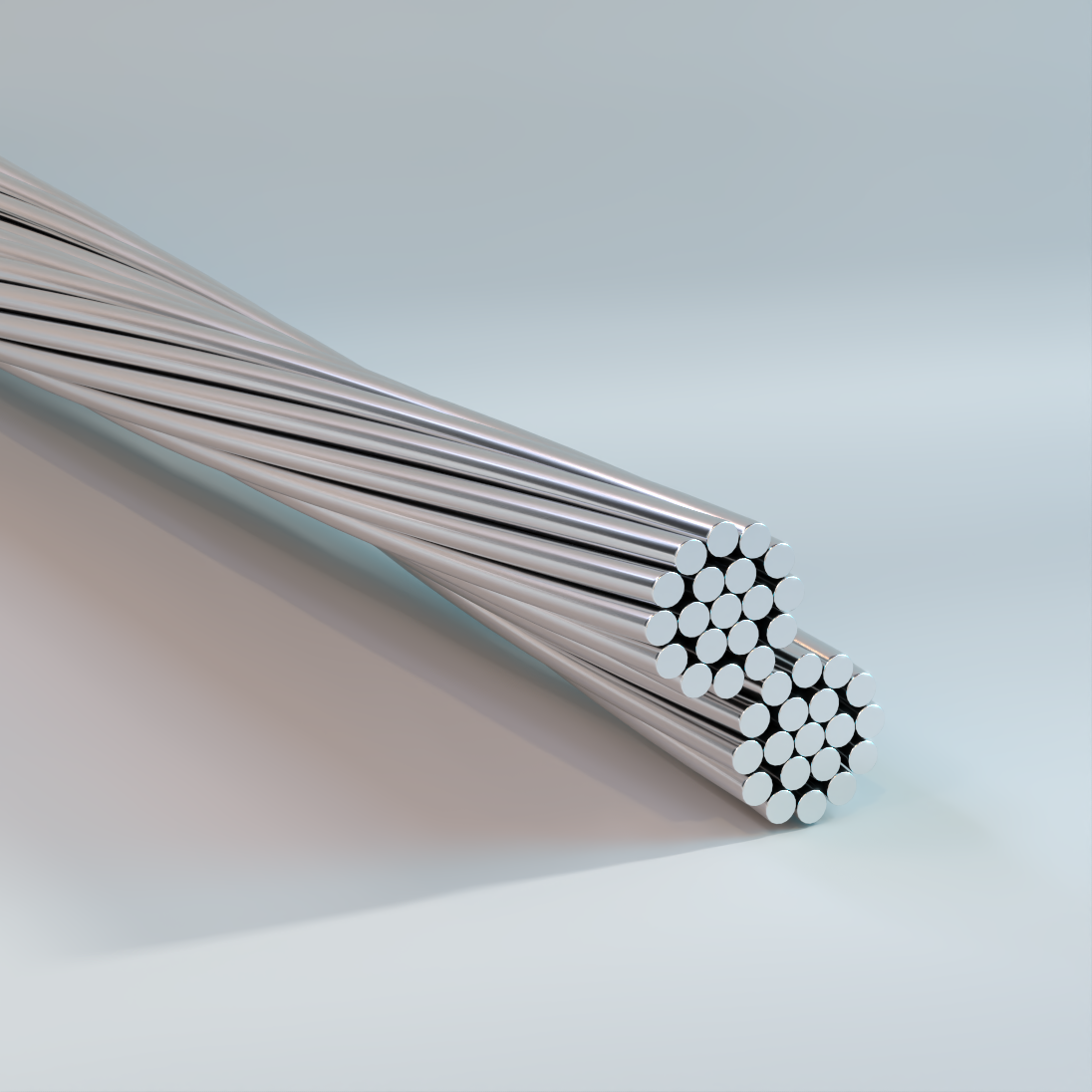
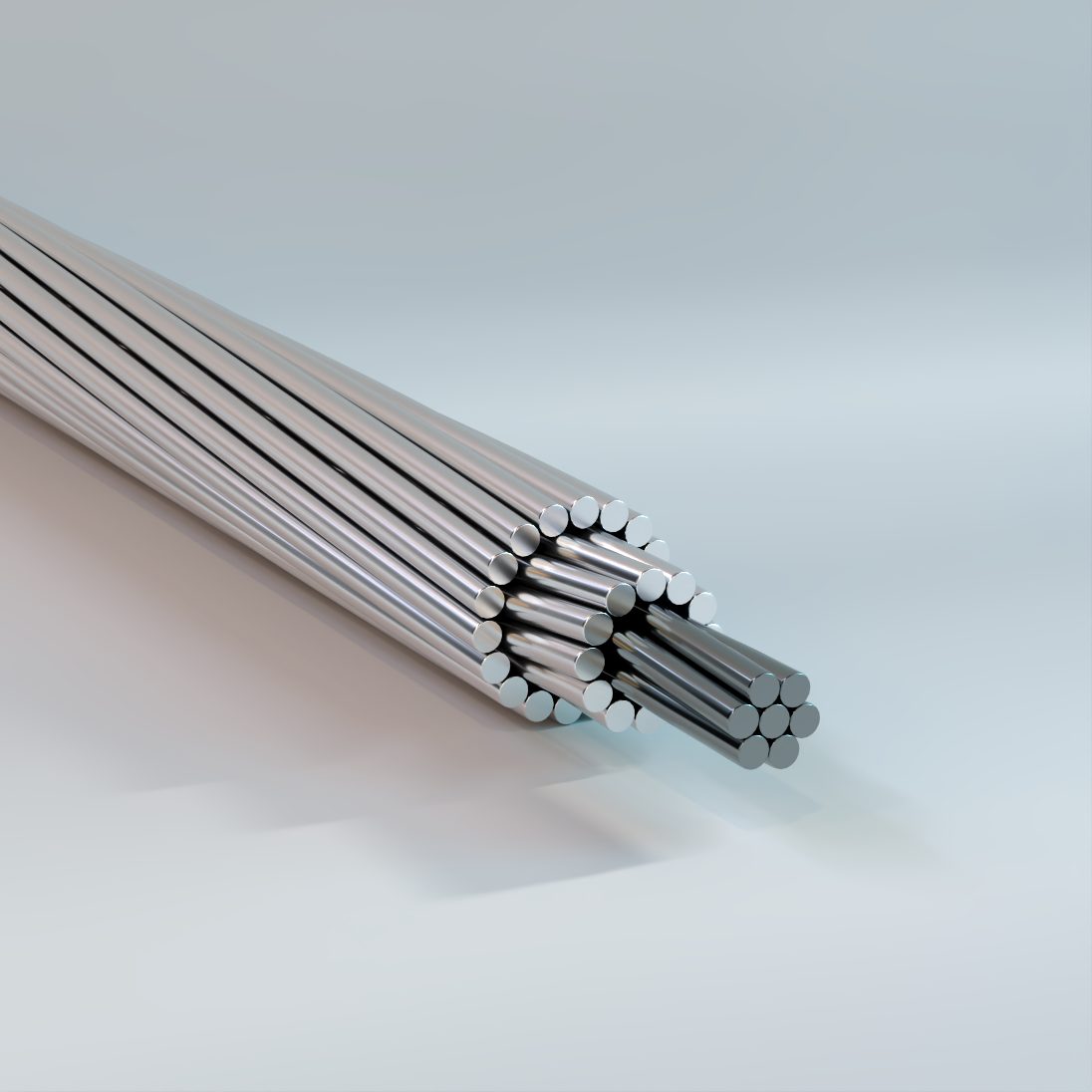
AAC
All Aluminum, Bare Overhead Concentric Lay Stranded Conductors
Used as overhead electrical energy conductors to maximimize the current carrying capacity for transmission and distribution projects that don’t require the strength of ACSR type conductors. Also, AAC is a good choice for coastal areas where the environmental conditions are corrosive to ACSR conductors.
Physical Data
| AAC | ||||||||||||||
|---|---|---|---|---|---|---|---|---|---|---|---|---|---|---|
| Code Word | Size AWG or kcmil | Cross Sectional Area in2 | Class | Stranding | Physical Properties | Electrical Properties | ||||||||
| Number | Diameter | Nominal Conductor Diameter | Rated Strength | Nominal Mass | Resistance | Reactance | ||||||||
| in | in | lb | lb/kft | dc20°C | ac25°C | ac75°C | Capacitive | Inductive | GMR | |||||
| Ω/kft | Ω/kft | Ω/k ft | MΩ/kft | Ω/kft | ft | |||||||||
| Peachbell | 6 | 0.0206 | A | 7 | 0.0612 | 0.184 | 563 | 24.6 | 0.6593 | 0.6725 | 0.80 59 | 0.766 | 0.1193 | 0.00555 |
| Rose | 4 | 0.0328 | A | 7 | 0.0772 | 0.232 | 881 | 39.1 | 0.4144 | 0.4227 | 0.50 64 | 0.7296 | 0.114 | 0.007 |
| Iris | 2 | 0.0522 | AA,A | 7 | 0.0974 | 0.292 | 1350 | 62.2 | 0.2602 | 0.2655 | 0.31 82 | 0.6929 | 0.1087 | 0.00883 |
| Pansy | 1 | 0.0657 | AA,A | 7 | 0.1093 | 0.328 | 1640 | 78.4 | 0.2066 | 0.211 | 0.25 27 | 0.6716 | 0.1061 | 0.00991 |
| Poppy | 1/0 | 0.0829 | AA,A | 7 | 0.1228 | 0.368 | 1990 | 98.9 | 0.1638 | 0.1671 | 0.20 02 | 0.655 | 0.1034 | 0.0111 |
| Aster | 2/0 | 0.1045 | AA,A | 7 | 0.1379 | 0.414 | 2510 | 124.8 | 0.1299 | 0.1326 | 0.15 87 | 0.6346 | 0.1008 | 0.0125 |
| Phlox | 3/0 | 0.1317 | AA,A | 7 | 0.1548 | 0.464 | 3040 | 157.2 | 0.1031 | 0.1053 | 0.12 59 | 0.6188 | 0.0981 | 0.014 |
| Oxlip | 4/0 | 0.1662 | AA,A | 7 | 0.1739 | 0.522 | 3830 | 198.4 | 0.0817 | 0.0835 | 0.10 00 | 0.6029 | 0.0955 | 0.0158 |
| Sneezewort | 250 | 0.1964 | AA | 7 | 0.189 | 0.567 | 4520 | 234.4 | 0.0691 | 0.0706 | 0.08 47 | 0.586 | 0.0934 | 0.0171 |
| Valerian | 250 | 0.1963 | A | 19 | 0.1147 | 0.574 | 4660 | 234.3 | 0.0691 | 0.0706 | 0.08 47 | 0.586 | 0.0922 | 0.0181 |
| Daisy | 266.8 | 0.2095 | AA | 7 | 0.1952 | 0.586 | 4830 | 250.2 | 0.0648 | 0.0663 | 0.07 94 | 0.581 | 0.0926 | 0.0177 |
| Laurel | 266.8 | 0.2095 | A | 19 | 0.1185 | 0.593 | 4970 | 250.1 | 0.0648 | 0.0663 | 0.0794 | 0.581 | 0.0915 | 0.0187 |
| Peony | 300 | 0.2358 | A | 19 | 0.1257 | 0.629 | 5480 | 281.4 | 0.0575 | 0.0589 | 0.0705 | 0.57 | 0.0902 | 0.0198 |
| Tulip | 336.4 | 0.2644 | A | 19 | 0.1331 | 0.666 | 6150 | 315.5 | 0.0513 | 0.0527 | 0.0629 | 0.56 | 0.0888 | 0.021 |
| Daffodil | 350 | 0.2748 | A | 19 | 0.1357 | 0.679 | 6390 | 327.9 | 0.0494 | 0.0506 | 0.0606 | 0.56 | 0.0883 | 0.0214 |
| Canna | 397.5 | 0.3124 | AA,A | 19 | 0.1447 | 0.724 | 7110 | 372.9 | 0.0435 | 0.0445 | 0.0534 | 0.549 | 0.0869 | 0.0228 |
| Goldentuft | 450 | 0.3534 | AA | 19 | 0.1539 | 0.769 | 7890 | 421.8 | 0.0384 | 0.0394 | 0.0472 | 0.539 | 0.0854 | 0.0243 |
| Cosmos | 477 | 0.3744 | AA | 19 | 0.1584 | 0.792 | 8360 | 446.8 | 0.0363 | 0.0373 | 0.0445 | 0.533 | 0.0848 | 0.025 |
| Syringa | 477 | 0.3744 | A | 37 | 0.1135 | 0.795 | 8690 | 446.8 | 0.0363 | 0.0373 | 0.0445 | 0.533 | 0.0845 | 0.0254 |
| Zinnia | 500 | 0.3926 | AA | 19 | 0.1622 | 0.811 | 8760 | 468.5 | 0.0346 | 0.0356 | 0.0426 | 0.531 | 0.0843 | 0.0256 |
| The above data are approximate and subject to normal manufacturing tolerances. Where required, the compatibility with glands, connectors and accessories should be verified using actual dimensions of the product. Other sizes available upon request. Direct current resistance is based on 16.946 Ω·cmil/ft at 20°C, 61.2% IACS with stranding increments as per ASTM B231. |
||||||||||||||
| AAC (cont.) | ||||||||||||||
|---|---|---|---|---|---|---|---|---|---|---|---|---|---|---|
| Code Word |
Size AWG or kcmil |
Cross Sectional Area 2 |
Class | Stranding | Physical Properties | Electrical Properties | ||||||||
| Number | Diameter | Nominal Conductor Diameter |
Rated Strength |
Nominal Mass |
Resistance | Reactance | ||||||||
| in | in | lb | lb/kft | dc 20 °C | ac 25 °C | ac 75 °C | Capacitive | Inductive | GMR | |||||
| Ω/kft | Ω/kft | Ω/kft | MΩ/kft | Ω/kft | ft | |||||||||
| Dahlia | 556.5 | 0.4369 | AA | 19 | 0.1711 | 0.856 | 9750 | 521.4 | 0.0311 | 0.032 | 0.0383 | 0.522 | 0.083 | 0.027 |
| Mistletoe | 556.5 | 0.4368 | A | 37 | 0.1226 | 0.858 | 9940 | 521.3 | 0.0311 | 0.032 | 0.0383 | 0.522 | 0.0826 | 0.0275 |
| Meadowsweet | 600 | 0.4709 | AA,A | 37 | 0.1273 | 0.891 | 10700 | 562 | 0.0288 | 0.0297 | 0.0356 | 0.516 | 0.0818 | 0.0285 |
| Orchid | 636 | 0.4995 | AA,A | 37 | 0.1311 | 0.918 | 11400 | 596 | 0.0272 | 0.0282 | 0.0335 | 0.511 | 0.0811 | 0.0294 |
| Heuchera | 650 | 0.5102 | AA | 37 | 0.1325 | 0.928 | 11600 | 609.8 | 0.0266 | 0.0275 | 0.0324 | 0.51 | 0.0808 | 0.0297 |
| Verbena | 700 | 0.5494 | AA | 37 | 0.1375 | 0.963 | 12500 | 655.7 | 0.0247 | 0.0256 | 0.0305 | 0.504 | 0.0799 | 0.0308 |
| Violet | 715.5 | 0.5623 | AA | 37 | 0.1391 | 0.974 | 12800 | 671 | 0.0242 | 0.0252 | 0.0299 | 0.502 | 0.0797 | 0.0312 |
| Nasturtium | 715.5 | 0.5619 | A | 61 | 0.1083 | 0.975 | 13100 | 671 | 0.0242 | 0.0252 | 0.0299 | 0.502 | 0.0795 | 0.0314 |
| Petunia | 750 | 0.5893 | AA | 37 | 0.1424 | 0.997 | 13100 | 703.2 | 0.023 | 0.0251 | 0.0286 | 0.498 | 0.0792 | 0.0319 |
| Arbutus | 795 | 0.6245 | AA | 37 | 0.1466 | 1.026 | 13900 | 745.3 | 0.0217 | 0.0227 | 0.0269 | 0.494 | 0.078 | 0.0328 |
| Lilac | 795 | 0.6248 | A | 61 | 0.1142 | 1.028 | 14300 | 745.7 | 0.0217 | 0.0227 | 0.0269 | 0.494 | 0.0784 | 0.0331 |
| Cockscomb | 900 | 0.7072 | AA | 37 | 0.156 | 1.092 | 16400 | 844 | 0.0192 | 0.0201 | 0.0239 | 0.484 | 0.0771 | 0.0349 |
| Magnolia | 954 | 0.7495 | AA | 37 | 0.1606 | 1.124 | 16400 | 894.5 | 0.0181 | 0.0191 | 0.0227 | 0.479 | 0.0763 | 0.036 |
| Goldenrod | 954 | 0.7498 | A | 61 | 0.1251 | 1.126 | 16900 | 894.8 | 0.0181 | 0.0191 | 0.0227 | 0.479 | 0.0763 | 0.0362 |
| Hawkweed | 1000 | 0.7854 | AA | 37 | 0.1644 | 1.151 | 17200 | 937.3 | 0.0173 | 0.0182 | 0.0216 | 0.476 | 0.0759 | 0.0368 |
| Bluebell | 1033.5 | 0.8114 | AA | 37 | 0.1671 | 1.17 | 17700 | 968.4 | 0.0167 | 0.0177 | 0.021 | 0.473 | 0.0756 | 0.0374 |
| Larkspur | 1033.5 | 0.8122 | A | 61 | 0.1302 | 1.172 | 18300 | 969.2 | 0.0167 | 0.0177 | 0.021 | 0.473 | 0.0754 | 0.0377 |
| Marigold | 1113 | 0.8744 | AA,A | 61 | 0.1351 | 1.216 | 19700 | 1044 | 0.0155 | 0.0165 | 0.0195 | 0.467 | 0.0744 | 0.0391 |
| Hawthorn | 1192.5 | 0.9363 | AA,A | 61 | 0.1398 | 1.258 | 21100 | 1117 | 0.0145 | 0.0155 | 0.0183 | 0.462 | 0.0737 | 0.0405 |
| Narcissus | 1272 | 0.999 | AA,A | 61 | 0.1444 | 1.3 | 22000 | 1192 | 0.0136 | 0.0146 | 0.0173 | 0.457 | 0.0729 | 0.0418 |
| Columbine | 1351.5 | 1.061 | AA,A | 61 | 0.1488 | 1.34 | 23400 | 1266 | 0.0128 | 0.0138 | 0.0163 | 0.452 | 0.0722 | 0.0431 |
| Carnation | 1431 | 1.124 | AA,A | 61 | 0.1532 | 1.379 | 24300 | 1342 | 0.0121 | 0.0132 | 0.0155 | 0.447 | 0.0715 | 0.0444 |
| Coreopsis | 1590 | 1.248 | AA | 61 | 0.1614 | 1.454 | 27000 | 1489 | 0.0109 | 0.012 | 0.0141 | 0.439 | 0.0705 | 0.0468 |
| Jessamine | 1750 | 1.375 | AA | 61 | 0.1694 | 1.525 | 29700 | 1641 | 0.0099 | 0.0111 | 0.0129 | 0.432 | 0.0693 | 0.049 |
| Cowslip | 2000 | 1.57 | A | 91 | 0.1482 | 1.63 | 34200 | 1873 | 0.0087 | 0.0099 | 0.0115 | 0.421 | 0.0677 | 0.0525 |
| Sagebrush | 2250 | 1.766 | A | 91 | 0.1572 | 1.729 | 37700 | 2128 | 0.0078 | 0.0091 | 0.0105 | 0.412 | 0.0664 | 0.0557 |
| Lupine* | 2500 | 1.962 | A | 91 | 0.1657 | 1.823 | 41900 | 2365 | 0.007 | 0.0084 | 0.0097 | 0.404 | 0.0652 | 0.0588 |
| The above data are approximate and subject to normal manufacturing tolerances. Where required, the compatibility with glands, connectors and accessories should be verified using actual dimensions of the product. Other sizes available upon request. Direct current resistance is based on 16.946 Ω·cmil/ft at 20°C, 61.2% IACS with stranding increments as per ASTM B231. |
||||||||||||||
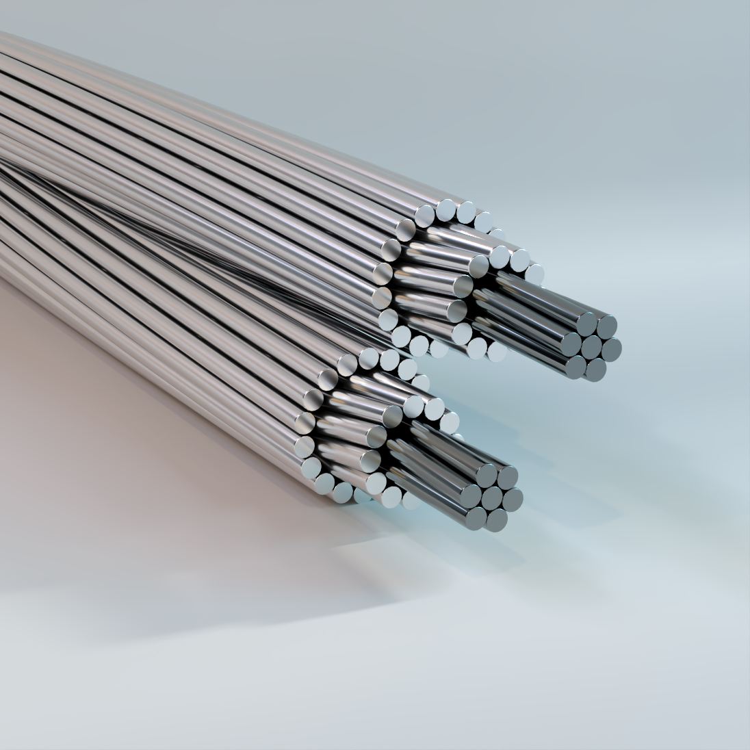
AAC-TP
All Aluminum, Bare Overhead Concentric Lay Stranded Conductors, Twisted Pair
Used as overhead electrical energy conductors. The two twisted cable configuration is used in applications subject to aeolian vibration and galloping due to wind and ice.
Physical Data
| AAC-TP | |||||||||||
|---|---|---|---|---|---|---|---|---|---|---|---|
| Code Word | Closest Size AWG or kcmil | Component Composition | Outer Dimensions | Nominal Mass | Rated Strength | Resistance | Ampacity | ||||
| AWG or kcmil | Number of Strands | Individual Wire OD |
Minor | Major | Ω/kft | ||||||
| in | in | in | lb/kft | lb | dc at 20 °C | ac at 75 °C | 75 °C | ||||
| Rose/TP | 1 | 4 | 7 | 0.0772 | 0.232 | 0.463 | 78 | 1762 | 0.0392 | 0.048 | 233.1 |
| Iris/TP | 2/0 | 2 | 7 | 0.0974 | 0.292 | 0.584 | 124 | 2700 | 0.0246 | 0.0301 | 312.7 |
| Pansy/TP | 3/0 | 1 | 7 | 0.1093 | 0.328 | 0.656 | 156 | 3280 | 0.0196 | 0.0239 | 361.1 |
| Poppy/TP | 4/0 | 1/0 | 7 | 0.1228 | 0.368 | 0.737 | 198 | 3980 | 0.0155 | 0.019 | 418.4 |
| Aster/TP | 266.8 | 2/0 | 7 | 0.1379 | 0.414 | 0.827 | 250 | 5020 | 0.0123 | 0.015 | 484.1 |
| Phlox/TP | 336.4 | 3/0 | 7 | 0.1548 | 0.464 | 0.929 | 314 | 6080 | 0.0098 | 0.0119 | 560.6 |
| Oxlip/TP | 397.5 | 4/0 | 7 | 0.1739 | 0.522 | 1.043 | 396 | 7660 | 0.0077 | 0.0095 | 648.1 |
| Daisy/TP | 500 | 266.8 | 7 | 0.1952 | 0.586 | 1.171 | 500 | 9660 | 0.0061 | 0.0075 | 749.2 |
| Laurel/TP | 500 | 266.8 | 19 | 0.1185 | 0.593 | 1.185 | 500 | 9940 | 0.0061 | 0.0075 | 751.5 |
| Tulip/TP | 636 | 336.4 | 19 | 0.1331 | 0.666 | 1.331 | 630 | 12300 | 0.0049 | 0.0059 | 871.6 |
| Canna/TP | 795 | 397.5 | 19 | 0.1446 | 0.723 | 1.446 | 746 | 14220 | 0.0041 | 0.0051 | 966.7 |
| Cosmos/TP | 954 | 477 | 19 | 0.1584 | 0.792 | 1.584 | 894 | 16720 | 0.0034 | 0.0042 | 1084.9 |
| Zinnia/TP | 954 | 500 | 19 | 0.1622 | 0.811 | 1.622 | 938 | 17520 | 0.0033 | 0.004 | 1115.8 |
| Dahlia/TP | 1113 | 557 | 19 | 0.1711 | 0.856 | 1.711 | 1044 | 19500 | 0.0029 | 0.0036 | 1194.5 |
| Orchid/TP | 1272 | 636 | 37 | 0.1311 | 0.918 | 1.835 | 1192 | 22800 | 0.0026 | 0.0032 | 1296.5 |
| Violet/TP | 1431 | 716 | 37 | 0.1391 | 0.974 | 1.947 | 1342 | 25600 | 0.0023 | 0.0028 | 1389.3 |
| Petunia/TP | 1431 | 750 | 37 | 0.1424 | 0.997 | 1.994 | 1406 | 26200 | 0.0022 | 0.0027 | 1383.4 |
| Arbutus/TP | 1590 | 795 | 37 | 0.1466 | 1.026 | 2.052 | 1490 | 27800 | 0.0021 | 0.0025 | 1495.6 |
| Magnolia/TP | 2000 | 954 | 37 | 0.1606 | 1.124 | 2.248 | 1788 | 32800 | 0.0017 | 0.0022 | 1670.7 |
| Bluebell/TP | 2000 | 1033.5 | 37 | 0.1671 | 1.17 | 2.339 | 1938 | 35400 | 0.0016 | 0.002 | 1758.6 |
| Marigold/TP | 2000 | 1113 | 61 | 0.1351 | 1.216 | 2.432 | 2086 | 39400 | 0.0015 | 0.0019 | 1847.7 |
| Hawthorn/TP* | 2250 | 1192.5 | 61 | 0.1398 | 1.258 | 2.516 | 2236 | 42200 | 0.0014 | 0.0017 | 1926.3 |
| The above data are approximate and subject to normal manufacturing tolerances. Other sizes available upon request. Direct current resistance is based on 16.946 Ω·cmil/ft (61.2% IACS) at 20°C for 1350 aluminum nominal area of conductor with standard stranding increments Per ASTM B231. † Ampacities are based on the following: Conductivity 61.2%, Ambient 25°C, Wind 2 ft/s, Sun, Sea level, Solar Absorption 0.5, Emissivity 0.5. |
|||||||||||
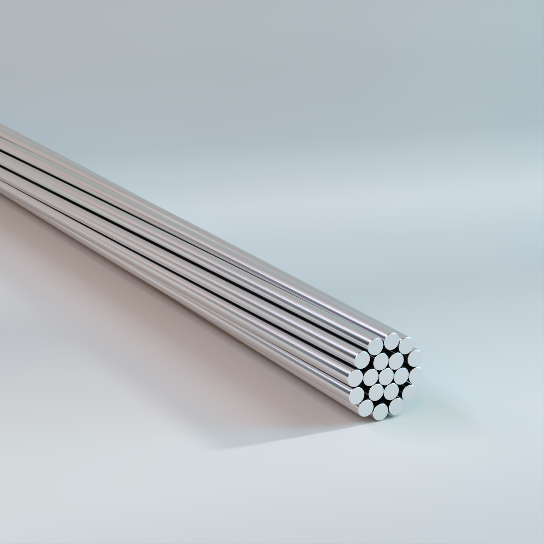
AAAC
All Aluminum Alloy, Bare Overhead Concentric Lay Stranded Conductors
Used as overhead electrical energy conductors to optimize the strength and the current carrying capacity for transmission and distribution projects for which AAC conductors do not provide the required strength and ACSR conductors are either not required or suitable.
Physical Data
| AAAC-6201 (cont.) | ||||||||||
|---|---|---|---|---|---|---|---|---|---|---|
| Code Word | Conductor Size | Conductor Area | Stranding | Nominal Diameter | ACSR with Equal Diameter | Physical Properties | ||||
| Number | Diameter | Size | Stranding | Strength | Mass | Size of Equiv. Resistance | ||||
| kcmil | in 2 | in | in | lb | lb | AWG/kcmil | ||||
| Akron | 30.58 | 0.024 | 7 | 0.0661 | 0.198 | 6 | 6/1 | 1,110 | 28.5 | 6 |
| Alton | 48.69 | 0.0382 | 7 | 0.0834 | 0.25 | 4 | 6/1 | 1,760 | 45.4 | 4 |
| Ames | 77.47 | 0.0608 | 7 | 0.1052 | 0.316 | 2 | 6/1 | 2,800 | 72.2 | 2 |
| Azusa | 123.3 | 0.0968 | 7 | 0.1327 | 0.398 | 1/0 | 6/1 | 4,270 | 114.9 | 1/0 |
| Anaheim | 155.4 | 0.1221 | 7 | 0.149 | 0.447 | 2/0 | 6/1 | 5,390 | 144.9 | 2/0 |
| Amherst | 195.7 | 0.1537 | 7 | 0.1672 | 0.502 | 3/0 | 6/1 | 6,790 | 182.5 | 3/0 |
| Alliance | 246.9 | 0.1939 | 7 | 0.1878 | 0.563 | 4/0 | 6/1 | 8,560 | 230.2 | 4/0 |
| Butte | 312.8 | 0.2456 | 19 | 0.1283 | 0.642 | 266.8 | 26/7 | 10,500 | 291.6 | 266.8 |
| Canton | 394.5 | 0.3099 | 19 | 0.1441 | 0.721 | 336.4 | 26/7 | 13,300 | 367.9 | 336.4 |
| Cairo | 465.4 | 0.3655 | 19 | 0.1565 | 0.783 | 397.5 | 26/7 | 15,600 | 433.9 | 397.5 |
| Darien | 559.5 | 0.4394 | 19 | 0.1716 | 0.858 | 477 | 26/7 | 18,800 | 521.7 | 477 |
| Elgin | 652.4 | 0.5124 | 19 | 0.1853 | 0.927 | 556.5 | 26/7 | 21,900 | 608.3 | 556.5 |
| Flint | 740.8 | 0.5818 | 37 | 0.1415 | 0.991 | 636 | 26/7 | 24,400 | 690.8 | 636 |
| Greeley | 927.2 | 0.7282 | 37 | 0.1583 | 1.108 | 795 | 26/7 | 30,500 | 864.6 | 795 |
| The above data are approximate and subject to normal manufacturing tolerances. Other sizes available upon request. Direct current resistance is based on 19.755 Ω·cmil/ft at 20°C (68°F), 52.5%IACS with stranding increment of 2 percent. |
||||||||||
| AAAC-6201 (cont.) | |||||||||||
|---|---|---|---|---|---|---|---|---|---|---|---|
| Stranding | Nominal Diameter | Electrical Properties | |||||||||
| Code Word |
Conductor Size |
Conductor Area |
Number | Diameter | Resistance | Reactance | |||||
| kcmil | in 2 | in | in | dc 20°C | ac 25°C | ac 75°C | Capacitive | Inductive | GMR | ||
| Ω/kft | Ω/kft | Ω/kft | MΩ/kft | Ω/kft | ft | ||||||
| Akron | 30.58 | 0.024 | 7 | 0.0661 | 0.198 | 0.6589 | 0.67 | 0.784 | 0.751 | 0.118 | 0.00599 |
| Alton | 48.69 | 0.0382 | 7 | 0.0834 | 0.25 | 0.4138 | 0.42 | 0.492 | 0.715 | 0.112 | 0.00756 |
| Ames | 77.47 | 0.0608 | 7 | 0.1052 | 0.316 | 0.26 | 0.265 | 0.311 | 0.678 | 0.107 | 0.00954 |
| Azusa | 123.3 | 0.0968 | 7 | 0.1327 | 0.398 | 0.1635 | 0.166 | 0.195 | 0.642 | 0.102 | 0.012 |
| Anaheim | 155.4 | 0.1221 | 7 | 0.149 | 0.447 | 0.1297 | 0.132 | 0.155 | 0.624 | 0.0989 | 0.0135 |
| Amherst | 195.7 | 0.1537 | 7 | 0.1672 | 0.502 | 0.103 | 0.105 | 0.123 | 0.606 | 0.0963 | 0.0152 |
| Alliance | 246.9 | 0.1939 | 7 | 0.1878 | 0.563 | 0.0816 | 0.0831 | 0.0973 | 0.588 | 0.0936 | 0.017 |
| Butte | 312.8 | 0.2456 | 19 | 0.1283 | 0.642 | 0.0644 | 0.0657 | 0.0769 | 0.567 | 0.0896 | 0.0202 |
| Canton | 394.5 | 0.3099 | 19 | 0.1441 | 0.721 | 0.0511 | 0.0523 | 0.061 | 0.549 | 0.087 | 0.0227 |
| Cairo | 465.4 | 0.3655 | 19 | 0.1565 | 0.783 | 0.0433 | 0.0443 | 0.0517 | 0.536 | 0.0851 | 0.0247 |
| Darien | 559.5 | 0.4394 | 19 | 0.1716 | 0.858 | 0.036 | 0.0369 | 0.0431 | 0.522 | 0.0829 | 0.0271 |
| Elgin | 652.4 | 0.5124 | 19 | 0.1853 | 0.927 | 0.0309 | 0.0318 | 0.0371 | 0.751 | 0.118 | 0.0292 |
| Flint | 740.8 | 0.5818 | 37 | 0.1415 | 0.991 | 0.0272 | 0.028 | 0.0328 | 0.715 | 0.112 | 0.0317 |
| Greeley | 927.2 | 0.7282 | 37 | 0.1583 | 1.108 | 0.0217 | 0.0225 | 0.0263 | 0.678 | 0.107 | 0.0354 |
| The above data are approximate and subject to normal manufacturing tolerances. Other sizes available upon request. Direct current resistance is based on 19.755 Ω·cmil/ft at 20°C (68°F), 52.5%IACS with stranding increment of 2 percent. |
|||||||||||
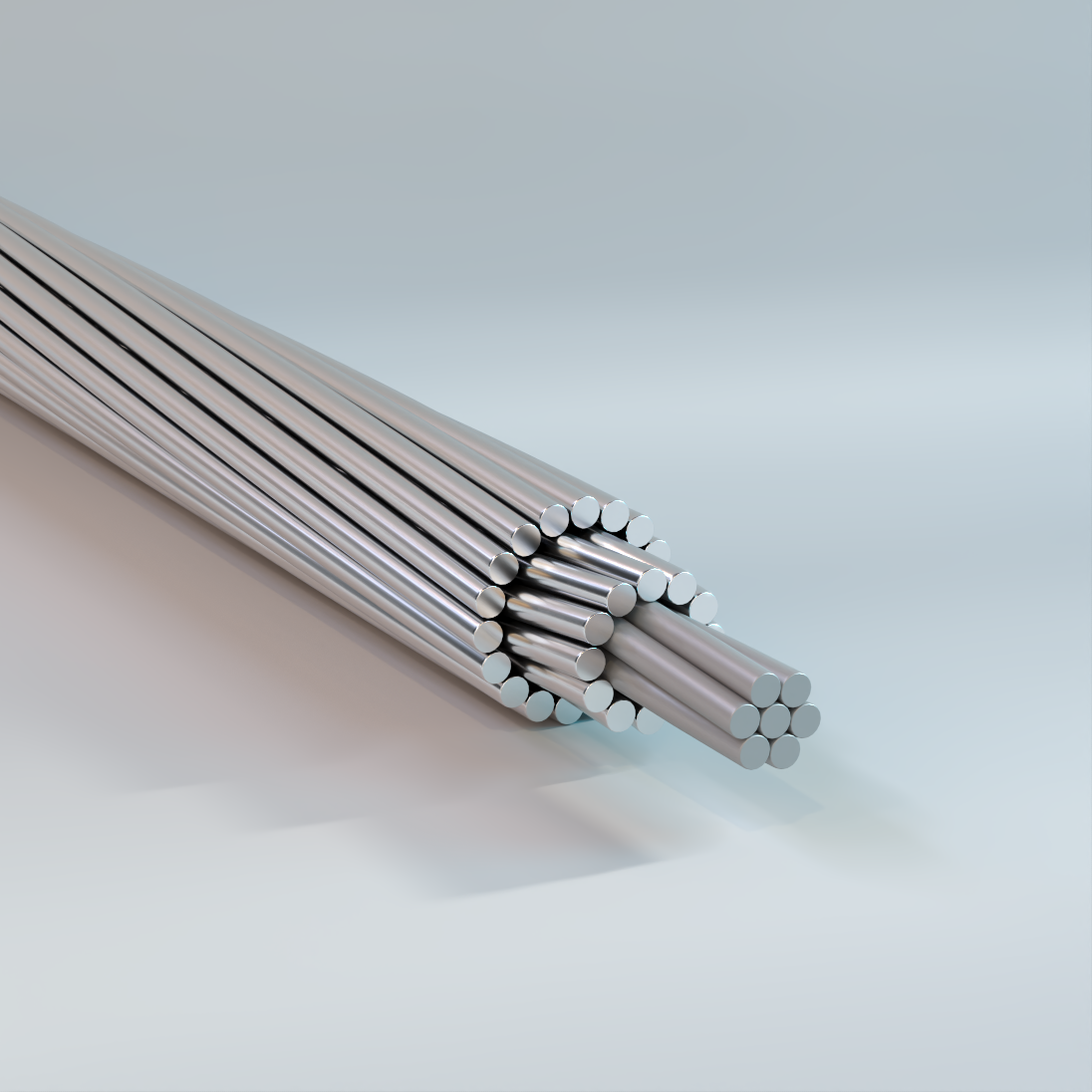
ACAR
Aluminum Conductor, Aluminum Reinforced, Bare Overhead Concentric Lay Stranded Conductors
Used as overhead electrical energy conductors to optimize the strength and the current carrying capacity for transmission and distribution projects for which AAC conductors do not provide the required strength and AAAC or ACSR conductors are either not required or suitable.
Physical Data
| ACAR | |||||||||||||||||
|---|---|---|---|---|---|---|---|---|---|---|---|---|---|---|---|---|---|
| Stranding | Cross Sectional Area | Physical Properties | Electrical Properties | ||||||||||||||
| 1350-H19 | 6201-T81 | Resistance | Reactance | ||||||||||||||
| Code Word |
ACAR Size kcmil |
No. | Diameter | No. | Diameter | 1350-H19 | 6201-T81 | Total | Nominal Conductor Diameter |
Rated Strength |
Nominal Mass |
dc 20 °C | ac 25 °C | ac 75 °C | Capacitive | Inductive | GMR |
| in | in | in^{2} | in | kip | lb/kft | Ω/kft | Ω/kft | Ω/kft | MΩ/kft | Ω/kft | ft | ||||||
| Pelican | 503.6 | 15 | 0.1628 | 4 | 0.1628 | 0.3122 | 0.0833 | 0.3955 | 0.814 | 10.5 | 473 | 0.0354 | 0.0364 | 0.0433 | 0.531 | 0.0841 | 0.0257 |
| Osprey | 587.2 | 15 | 0.1758 | 4 | 0.1758 | 0.3641 | 0.0971 | 0.4612 | 0.879 | 12.2 | 551 | 0.0303 | 0.0312 | 0.0371 | 0.518 | 0.0824 | 0.0277 |
| Dove | 649.5 | 18 | 0.1325 | 19 | 0.1325 | 0.2482 | 0.2620 | 0.5102 | 0.927 | 16.6 | 608 | 0.0287 | 0.0295 | 0.0349 | 0.509 | 0.0812 | 0.0292 |
| Dove | 653.1 | 12 | 0.1854 | 7 | 0.1854 | 0.3240 | 0.1890 | 0.5130 | 0.927 | 15.4 | 612 | 0.0279 | 0.0288 | 0.0341 | 0.509 | 0.0811 | 0.0293 |
| Grosbeak | 739.8 | 18 | 0.1414 | 19 | 0.1414 | 0.2827 | 0.2983 | 0.5810 | 0.990 | 18.8 | 693 | 0.0252 | 0.0259 | 0.0307 | 0.499 | 0.0793 | 0.0317 |
| Tern | 853.7 | 30 | 0.1519 | 7 | 0.1519 | 0.5437 | 0.1268 | 0.6705 | 1.063 | 17.5 | 801 | 0.0208 | 0.0216 | 0.0257 | 0.488 | 0.0777 | 0.0340 |
| Tern | 853.7 | 24 | 0.1519 | 13 | 0.1519 | 0.4349 | 0.2356 | 0.6705 | 1.063 | 19.3 | 800 | 0.0213 | 0.0222 | 0.0262 | 0.488 | 0.0777 | 0.0340 |
| Drake | 927.2 | 24 | 0.1583 | 13 | 0.1583 | 0.4723 | 0.2559 | 0.7282 | 1.108 | 20.9 | 869 | 0.0208 | 0.0216 | 0.0252 | 0.482 | 0.0767 | 0.0355 |
| Rail | 1024.5 | 30 | 0.1664 | 7 | 0.1664 | 0.6524 | 0.1522 | 0.8046 | 1.165 | 20.9 | 961 | 0.0173 | 0.0182 | 0.0215 | 0.474 | 0.0756 | 0.0373 |
| Rail | 1024.5 | 24 | 0.1664 | 13 | 0.1664 | 0.5219 | 0.2827 | 0.8046 | 1.165 | 23.1 | 961 | 0.0178 | 0.0186 | 0.0219 | 0.474 | 0.0756 | 0.0373 |
| Cardinal | 1080.6 | 24 | 0.1709 | 13 | 0.1709 | 0.5505 | 0.2982 | 0.8487 | 1.196 | 24.4 | 1013 | 0.0168 | 0.0176 | 0.0208 | 0.470 | 0.0750 | 0.0383 |
| Cardinal | 1080.6 | 18 | 0.1709 | 19 | 0.1709 | 0.4129 | 0.4358 | 0.8487 | 1.196 | 27.2 | 1012 | 0.0172 | 0.0181 | 0.0213 | 0.470 | 0.0750 | 0.0383 |
| Ortolan | 1109.0 | 30 | 0.1731 | 7 | 0.1731 | 0.7060 | 0.1647 | 0.8707 | 1.212 | 22.7 | 1041 | 0.0160 | 0.0169 | 0.0199 | 0.468 | 0.0747 | 0.0388 |
| Ortolan | 1109.0 | 24 | 0.1731 | 13 | 0.1731 | 0.5648 | 0.3059 | 0.8707 | 1.212 | 25.0 | 1040 | 0.0164 | 0.0172 | 0.0203 | 0.468 | 0.0747 | 0.0388 |
| Curlew | 1172.0 | 30 | 0.1780 | 7 | 0.1780 | 0.7465 | 0.1742 | 0.9207 | 1.246 | 24.0 | 1100 | 0.0152 | 0.0160 | 0.0189 | 0.463 | 0.0740 | 0.0399 |
| Curlew | 1172.0 | 18 | 0.1780 | 19 | 0.1780 | 0.4479 | 0.4728 | 0.9207 | 1.246 | 29.5 | 1098 | 0.0159 | 0.0166 | 0.0195 | 0.463 | 0.0740 | 0.0399 |
| Bluejay | 1198.0 | 30 | 0.1799 | 7 | 0.1799 | 0.7626 | 0.1779 | 0.9405 | 1.259 | 24.5 | 1124 | 0.0148 | 0.0155 | 0.0184 | 0.462 | 0.0738 | 0.0403 |
| Bluejay | 1198.0 | 24 | 0.1799 | 13 | 0.1799 | 0.6101 | 0.3304 | 0.9405 | 1.259 | 27.1 | 1123 | 0.0152 | 0.0159 | 0.0188 | 0.462 | 0.0738 | 0.0403 |
| Bunting | 1277.0 | 54 | 0.1447 | 7 | 0.1447 | 0.8880 | 0.1151 | 1.0031 | 1.302 | 24.6 | 1199 | 0.0138 | 0.0149 | 0.0174 | 0.456 | 0.0729 | 0.0419 |
| Bunting | 1277.0 | 42 | 0.1447 | 19 | 0.1447 | 0.6907 | 0.3124 | 1.0031 | 1.302 | 28.4 | 1198 | 0.0142 | 0.0152 | 0.0178 | 0.456 | 0.0729 | 0.0419 |
| Bittern | 1361.5 | 54 | 0.1494 | 7 | 0.1494 | 0.9466 | 0.1227 | 1.0693 | 1.345 | 26.3 | 1278 | 0.0129 | 0.0138 | 0.0163 | 0.451 | 0.0721 | 0.0433 |
| Bobolink | 1534.4 | 42 | 0.1586 | 19 | 0.1586 | 0.8297 | 0.3754 | 1.2051 | 1.427 | 33.8 | 1439 | 0.0118 | 0.0127 | 0.0152 | 0.442 | 0.0708 | 0.0459 |
| Lapwing | 1703.0 | 48 | 0.1671 | 13 | 0.1671 | 1.0527 | 0.2851 | 1.3378 | 1.504 | 34.6 | 1598 | 0.0105 | 0.0115 | 0.0135 | 0.434 | 0.0696 | 0.0484 |
| Falcon | 1798.0 | 42 | 0.1717 | 19 | 0.1717 | 0.9725 | 0.4399 | 1.4124 | 1.545 | 39.6 | 1686 | 0.0101 | 0.0110 | 0.0128 | 0.430 | 0.0690 | 0.0497 |
| Chukar | 1933.0 | 42 | 0.1780 | 19 | 0.1780 | 1.0452 | 0.4728 | 1.5180 | 1.602 | 42.5 | 1813 | 0.0094 | 0.0102 | 0.0122 | 0.424 | 0.0682 | 0.0515 |
| Bluebird* | 2338.0 | 42 | 0.1958 | 19 | 0.1958 | 1.2646 | 0.5721 | 1.8367 | 1.762 | 51.5 | 2214 | 0.0078 | 0.0089 | 0.0103 | 0.409 | 0.0660 | 0.0567 |
| Bluebird* | 2338.0 | 48 | 0.1958 | 13 | 0.1958 | 1.4453 | 0.3914 | 1.8367 | 1.762 | 47.5 | 2215 | 0.0077 | 0.0088 | 0.0102 | 0.409 | 0.0660 | 0.0567 |
| Kingfisher* | 2493.0 | 54 | 0.1655 | 37 | 0.1655 | 1.1617 | 0.7959 | 1.9576 | 1.821 | 57.6 | 2358 | 0.0074 | 0.0087 | 0.0100 | 0.404 | 0.0652 | 0.0587 |
| Kingfisher* | 2493.0 | 72 | 0.1655 | 19 | 0.1655 | 1.5489 | 0.4087 | 1.9576 | 1.821 | 50.4 | 2362 | 0.0072 | 0.0085 | 0.0098 | 0.404 | 0.0652 | 0.0587 |
| The above data are approximate and subject to normal manufacturing tolerances. Other sizes available upon request.
Direct current resistance is based on electrical resistivity of 16.946 Ω·cmil/ft at 20 °C (61.2% IACS) for 1350-H19 wires and 19.755 Ω·cmil/ft. at 20 °C (52.5% IACS) for 6201 wires. |
|||||||||||||||||
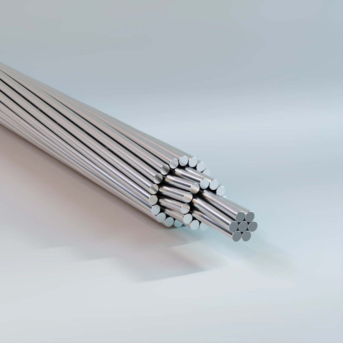
ACSR
Aluminum Conductor, Steel Reinforced, Bare Overhead Concentric Lay Stranded Conductors
Used for overhead power transmission and distribution projects. It’s a preferred choice due to it’s favorable strength/weight ratio, achieved by the lightweight, strong conductivity of aluminum coupled with the high tensile strength of steel.
Physical Data
| ACSR (cont.) | ||||||||||||||||||
|---|---|---|---|---|---|---|---|---|---|---|---|---|---|---|---|---|---|---|
| Code Word |
Size AWG or kcmil |
Stranding | Nominal Overall Diameter |
Cross Section | Mass | Rated Strength |
Resistance | Reactance | Ampacity | |||||||||
| Al | Steel | Al | Steel Core |
Al | Total | Al | Steel | Total | GA2 | GA3 | GA5 | DC | AC | Capacitive | Inductive | A | ||
| No. Wires x Size |
No. Wires x Size |
in | in 2 | lb/kft | lb/kft | lb/kft | lb | lb | lb | 20 °C | 75 °C | MΩ/kft | Ω/kft | |||||
| Ω/kft | Ω/kft | |||||||||||||||||
| Turkey | 6 | 6×0.0661 | 1×0.0661 | 0.198 | 0.0661 | 0.0206 | 0.024 | 24.4 | 11.6 | 36 | 1190 | 1260 | 1320 | 0.6419 | 0.8159 | 0.7513 | 0.1439 | 105 |
| Swan | 4 | 6×0.0834 | 1×0.0834 | 0.25 | 0.0834 | 0.0328 | 0.0382 | 39 | 18.4 | 57.4 | 1860 | 1970 | 2070 | 0.4032 | 0.5218 | 0.7149 | 0.1369 | 140 |
| Swanate | 4 | 7×0.0772 | 1×0.1029 | 0.257 | 0.1029 | 0.0328 | 0.0411 | 39 | 28 | 67 | 2360 | 2520 | 2680 | 0.3989 | 0.5165 | 0.7102 | 0.1303 | 139 |
| Sparrow | 2 | 6×0.1052 | 1×0.1052 | 0.316 | 0.1052 | 0.0522 | 0.0608 | 61.9 | 29.3 | 91.2 | 2850 | 3010 | 3180 | 0.2534 | 0.336 | 0.6785 | 0.1277 | 185 |
| Sparate | 2 | 7×0.0974 | 1×0.1299 | 0.325 | 0.1299 | 0.0522 | 0.0654 | 61.9 | 44.7 | 106.6 | 3640 | 3900 | 4150 | 0.2506 | 0.3297 | 0.6737 | 0.1206 | 184 |
| Robin | 1 | 6×0.1181 | 1×0.1181 | 0.354 | 0.1181 | 0.0657 | 0.0767 | 78.1 | 36.9 | 115 | 3550 | 3760 | 3980 | 0.2011 | 0.2703 | 0.66 | 0.1224 | 210 |
| Raven | 1/0 | 6×0.1327 | 1×0.1327 | 0.398 | 0.1327 | 0.083 | 0.0968 | 98.6 | 46.6 | 145.2 | 4380 | 4650 | 4910 | 0.1593 | 0.2161 | 0.6421 | 0.1163 | 240 |
| Quail | 2/0 | 6×0.1489 | 1×0.1489 | 0.447 | 0.1489 | 0.1045 | 0.1219 | 124.1 | 58.7 | 182.8 | 5300 | 5720 | 6050 | 0.1265 | 0.176 | 0.6241 | 0.1135 | 275 |
| Pigeon | 3/0 | 6×0.1672 | 1×0.1672 | 0.502 | 0.1672 | 0.1317 | 0.1537 | 156.4 | 74.1 | 230.5 | 6620 | 7150 | 7570 | 0.1003 | 0.1445 | 0.6056 | 0.1095 | 315 |
| Penguin | 4/0 | 6×0.1878 | 1×0.1878 | 0.563 | 0.1878 | 0.1662 | 0.1939 | 197.4 | 93.4 | 290.8 | 8350 | 9010 | 9550 | 0.0795 | 0.1157 | 0.5966 | 0.1053 | 360 |
| Waxwing | 266.8 | 18×0.1217 | 1×0.1217 | 0.609 | 0.1217 | 0.2094 | 0.221 | 249.9 | 39.2 | 289.1 | 6880 | 7100 | 7320 | 0.0644 | 0.0788 | 0.576 | 0.0934 | 450 |
| Partridge | 266.8 | 26×0.1013 | 7×0.0788 | 0.642 | 0.2364 | 0.2095 | 0.2437 | 251.3 | 115.6 | 366.9 | 11300 | 11900 | 12600 | 0.0637 | 0.0778 | 0.565 | 0.0881 | 455 |
| Merlin | 336.4 | 18×0.1367 | 1×0.1367 | 0.684 | 0.1367 | 0.2642 | 0.2789 | 315.3 | 49.5 | 364.8 | 8680 | 8960 | 9240 | 0.051 | 0.0625 | 0.56 | 0.0877 | 520 |
| Linnet | 336.4 | 26×0.1137 | 7×0.0884 | 0.72 | 0.2652 | 0.264 | 0.307 | 316.5 | 145.5 | 462 | 14100 | 14900 | 15700 | 0.0506 | 0.0619 | 0.549 | 0.0854 | 530 |
| Oriole | 336.4 | 30×0.1059 | 7×0.1059 | 0.741 | 0.3177 | 0.2642 | 0.3259 | 317.7 | 208.7 | 526.4 | 17300 | 18500 | 19700 | 0.0502 | 0.0614 | 0.544 | 0.0843 | 535 |
| Chickadee | 397.5 | 18×0.1486 | 1×0.1486 | 0.743 | 0.1486 | 0.3122 | 0.3295 | 372.5 | 58.5 | 431 | 9940 | 10400 | 10700 | 0.0432 | 0.0528 | 0.544 | 0.0856 | 577 |
| Ibis | 397.5 | 26×0.1236 | 7×0.0961 | 0.783 | 0.2883 | 0.312 | 0.3627 | 374.1 | 171.9 | 546 | 16300 | 17200 | 18200 | 0.0428 | 0.0525 | 0.539 | 0.0835 | 585 |
| Lark | 397.5 | 30×0.1151 | 7×0.1151 | 0.806 | 0.3453 | 0.3121 | 0.385 | 375.2 | 246.6 | 621.8 | 20300 | 21700 | 23100 | 0.0425 | 0.0519 | 0.533 | 0.0824 | 595 |
| Pelican | 477 | 18×0.1628 | 1×0.1628 | 0.814 | 0.1628 | 0.3747 | 0.3955 | 447.1 | 70.2 | 517.3 | 11800 | 12300 | 12700 | 0.036 | 0.0441 | 0.528 | 0.0835 | 645 |
| Flicker | 477 | 24×0.141 | 7×0.094 | 0.846 | 0.282 | 0.3747 | 0.4233 | 449.4 | 164.5 | 613.9 | 17200 | 18100 | 19000 | 0.0358 | 0.0439 | 0.524 | 0.0818 | 655 |
| Hawk | 477 | 26×0.1354 | 7×0.1053 | 0.858 | 0.3159 | 0.3744 | 0.4353 | 448.9 | 206.4 | 655.3 | 19500 | 20700 | 21900 | 0.0357 | 0.0438 | 0.522 | 0.0814 | 660 |
| Hen | 477 | 30×0.1261 | 7×0.1261 | 0.883 | 0.3783 | 0.3747 | 0.4621 | 450.4 | 296 | 746.4 | 23800 | 25500 | 27200 | 0.0354 | 0.0434 | 0.517 | 0.0803 | 665 |
| Osprey | 556.5 | 18×0.1758 | 1×0.1758 | 0.879 | 0.1758 | 0.4369 | 0.4612 | 521.4 | 81.9 | 603.3 | 13700 | 14300 | 14800 | 0.0309 | 0.0379 | 0.518 | 0.0818 | 710 |
| Parakeet | 556.5 | 24×0.1523 | 7×0.1015 | 0.914 | 0.3045 | 0.4372 | 0.4939 | 524.3 | 191.8 | 716.1 | 19800 | 20900 | 22000 | 0.0307 | 0.0377 | 0.512 | 0.0801 | 720 |
| Dove | 556.5 | 26×0.1463 | 7×0.1138 | 0.927 | 0.3414 | 0.4371 | 0.5083 | 524.2 | 241 | 765.2 | 22600 | 24000 | 25300 | 0.0305 | 0.0375 | 0.51 | 0.0795 | 725 |
| Eagle | 556.5 | 30×0.1362 | 7×0.1362 | 0.953 | 0.4086 | 0.4371 | 0.5391 | 525.4 | 345.3 | 870.7 | 27800 | 29700 | 31700 | 0.03 | 0.0371 | 0.505 | 0.0786 | 735 |
| Peacock | 605 | 24×0.1588 | 7×0.1059 | 0.953 | 0.3177 | 0.4745 | 0.537 | 570.1 | 208.7 | 778.8 | 21600 | 22700 | 23900 | 0.0282 | 0.0347 | 0.505 | 0.0792 | 760 |
| Swift | 636 | 36×0.1329 | 1×0.1329 | 0.93 | 0.1329 | 0.4994 | 0.5133 | 596 | 46.8 | 642.8 | 13800 | 14000 | 14300 | 0.0267 | 0.0334 | 0.509 | 0.0806 | 770 |
| Kingbird | 636 | 18×0.188 | 1×0.188 | 0.94 | 0.188 | 0.4997 | 0.5274 | 596.3 | 93.6 | 689.9 | 15700 | 16300 | 16900 | 0.0269 | 0.0332 | 0.507 | 0.0805 | 774 |
| Rook | 636 | 24×0.1628 | 7×0.1085 | 0.977 | 0.3255 | 0.4996 | 0.5643 | 599.1 | 219.1 | 818.2 | 22600 | 23900 | 25100 | 0.0268 | 0.033 | 0.502 | 0.0786 | 785 |
| Grosbeak | 636 | 26×0.1564 | 7×0.1216 | 0.99 | 0.3648 | 0.4995 | 0.5808 | 599 | 275.2 | 874.2 | 25200 | 26800 | 28300 | 0.0267 | 0.0328 | 0.5 | 0.078 | 790 |
| Egret | 636 | 30×0.1456 | 19×0.0874 | 1.019 | 0.437 | 0.4995 | 0.6135 | 600.5 | 386.7 | 987.2 | 31500 | 33600 | 35800 | 0.0266 | 0.0326 | 0.495 | 0.0769 | 795 |
| Flamingo | 666.6 | 24×0.1667 | 7×0.1111 | 1 | 0.3333 | 0.5238 | 0.5917 | 628.2 | 229.7 | 857.9 | 23700 | 25000 | 26300 | 0.0256 | 0.0314 | 0.498 | 0.078 | 810 |
| 1. Code words shown are for standard ACSR/GA2 conductor. See the options for other applicable code word modifiers. 2. Rated strengths shown are applicable for ACSR/GA2 and ACSR/MA2 cores. 3. Direct current resistance is based on 61.2% IACS for 1350 wires (ASTM B230) and 8% IACS for the steel core (ASTM B498) at 20 °C using stranding increment as per ASTM B232. 4. Consult IEEE 738: Standard for Calculating the Current-Temperature of Bare Overhead Conductors5. Based on a conductor temperature of 75°C, ambient temperature 25°C, wind 2 ft/sec, exposed to sun and wind. 6. The data are an estimate based on given criteria and subject to normal manufacturing tolerances. 7. Reactance is based on 1 ft equivalent spacing. |
||||||||||||||||||
| ACSR (cont.) | ||||||||||||||||||
|---|---|---|---|---|---|---|---|---|---|---|---|---|---|---|---|---|---|---|
| Code Word |
Size AWG or kcmil |
Stranding Al | Steel | Nominal Overall Diameter |
Cross Section | Mass | Rated Strength |
Resistance | Reactance | Ampacity | ||||||||
| No. Wires x Size |
No. Wires x Size |
Al | Steel Core |
Al | Total | Al | Steel | Total | GA2 | GA3 | GA5 | DC | AC | Capacitive | Inductive | A | ||
| in | in 2 | lb/kft | lb/kft | lb/kft | lb | lb | lb | 20 °C | 75 °C | MΩ/kft | Ω/kft | |||||||
| Ω/kft | Ω/kft | |||||||||||||||||
| Starling | 715.5 | 26×0.1659 | 7×0.129 | 1.051 | 0.387 | 0.562 | 0.6535 | 674 | 309.7 | 983.7 | 28400 | 30100 | 31900 | 0.0238 | 0.0292 | 0.49 | 0.0767 | 850 |
| Redwing | 715.5 | 30×0.1544 | 19×0.0926 | 1.081 | 0.463 | 0.5617 | 0.6897 | 675.3 | 434 | 1109.3 | 34600 | 36900 | 39300 | 0.0236 | 0.029 | 0.486 | 0.0756 | 860 |
| Coot | 795 | 36×0.1486 | 1×0.1486 | 1.04 | 0.1486 | 0.6244 | 0.6417 | 745.1 | 58.5 | 803.6 | 16800 | 17200 | 17500 | 0.0217 | 0.0268 | 0.492 | 0.078 | 884 |
| Tern | 795 | 45×0.1329 | 7×0.0886 | 1.063 | 0.2658 | 0.6242 | 0.6674 | 749 | 146 | 895 | 22100 | 22900 | 23700 | 0.0216 | 0.0267 | 0.488 | 0.0764 | 885 |
| Cuckoo | 795 | 24×0.182 | 7×0.1213 | 1.092 | 0.3639 | 0.6244 | 0.7053 | 749 | 274 | 1023 | 27900 | 29500 | 31000 | 0.0215 | 0.0266 | 0.484 | 0.0763 | 902 |
| Condor | 795 | 54×0.1213 | 7×0.1213 | 1.092 | 0.3639 | 0.624 | 0.7049 | 748 | 274 | 1022 | 28200 | 29700 | 31300 | 0.0215 | 0.0265 | 0.484 | 0.0759 | 895 |
| Drake | 795 | 26×0.1749 | 7×0.136 | 1.108 | 0.408 | 0.6247 | 0.7263 | 749 | 344 | 1093 | 31500 | 33500 | 35400 | 0.0214 | 0.0263 | 0.482 | 0.0756 | 905 |
| Mallard | 795 | 30×0.1628 | 19×0.0977 | 1.14 | 0.4885 | 0.6245 | 0.7669 | 750.7 | 483.2 | 1233.9 | 38400 | 41000 | 43700 | 0.0213 | 0.0261 | 0.477 | 0.0744 | 915 |
| Ruddy | 900 | 45×0.1414 | 7×0.0943 | 1.131 | 0.2829 | 0.7066 | 0.7555 | 848 | 165 | 1013 | 24400 | 25400 | 26300 | 0.0191 | 0.0237 | 0.479 | 0.0755 | 959 |
| Canary | 900 | 54×0.1291 | 7×0.1291 | 1.162 | 0.3873 | 0.7069 | 0.7985 | 848 | 310 | 1158 | 31900 | 33700 | 35400 | 0.019 | 0.0235 | 0.474 | 0.0744 | 965 |
| Corncrake | 954 | 20×0.2184 | 7×0.0971 | 1.165 | 0.2913 | 0.7492 | 0.8011 | 899 | 175 | 1074 | 25600 | 26000 | 27600 | 0.018 | 0.0224 | 0.474 | 0.0751 | 997 |
| Redbird | 954 | 24×0.1994 | 7×0.1329 | 1.196 | 0.3987 | 0.7495 | 0.8466 | 899 | 329 | 1228 | 33500 | 35400 | 37200 | 0.0179 | 0.0221 | 0.47 | 0.0742 | 1010 |
| Rail | 954 | 45×0.1456 | 7×0.0971 | 1.165 | 0.2913 | 0.7492 | 0.8011 | 899 | 176 | 1075 | 25900 | 26900 | 27900 | 0.018 | 0.0223 | 0.474 | 0.0748 | 990 |
| Cardinal | 954 | 54×0.1329 | 7×0.1329 | 1.196 | 0.3987 | 0.7491 | 0.8462 | 898.4 | 328.7 | 1227.1 | 33800 | 35700 | 37600 | 0.0179 | 0.0222 | 0.47 | 0.0757 | 1005 |
| Ortolan | 1033.5 | 45×0.1515 | 7×0.101 | 1.212 | 0.303 | 0.8112 | 0.8673 | 973 | 190 | 1163 | 27700 | 26800 | 28200 | 0.0167 | 0.0208 | 0.468 | 0.0739 | 1040 |
| Curlew | 1033.5 | 54×0.1383 | 7×0.1383 | 1.245 | 0.4149 | 0.8112 | 0.9164 | 973 | 356 | 1329 | 36600 | 28800 | 29800 | 0.0165 | 0.0201 | 0.464 | 0.0729 | 1055 |
| Bluejay | 1113 | 45×0.1573 | 7×0.1049 | 1.259 | 0.3147 | 0.8745 | 0.935 | 1049 | 205 | 1254 | 29800 | 38600 | 40700 | 0.0155 | 0.0193 | 0.462 | 0.0731 | 1090 |
| Finch | 1113 | 54×0.1436 | 19×0.0862 | 1.293 | 0.431 | 0.8746 | 0.9854 | 1054 | 376 | 1430 | 39100 | 31000 | 32200 | 0.0154 | 0.0191 | 0.458 | 0.0702 | 1100 |
| Bunting | 1192.5 | 45×0.1628 | 7×0.1085 | 1.302 | 0.3255 | 0.9367 | 1.0014 | 1123 | 219 | 1342 | 32000 | 41200 | 43200 | 0.0144 | 0.0181 | 0.456 | 0.0723 | 1135 |
| Grackle | 1192.5 | 54×0.1486 | 19×0.0892 | 1.338 | 0.446 | 0.9365 | 1.0553 | 1128 | 403 | 1531 | 41900 | 33200 | 34400 | 0.0144 | 0.0179 | 0.452 | 0.071 | 1150 |
| Bittern | 1272 | 45×0.1681 | 7×0.1121 | 1.345 | 0.3363 | 0.9987 | 1.0678 | 1198 | 234 | 1432 | 34100 | 44100 | 46300 | 0.0135 | 0.017 | 0.451 | 0.072 | 1180 |
| Pheasant | 1272 | 54×0.1535 | 19×0.0921 | 1.382 | 0.4605 | 0.9993 | 1.1259 | 1205 | 429 | 1634 | 43600 | 35400 | 36700 | 0.0135 | 0.0169 | 0.447 | 0.07 | 1195 |
| Dipper | 1351.5 | 45×0.1733 | 7×0.1155 | 1.386 | 0.3465 | 1.0614 | 1.1348 | 1273 | 248 | 1521 | 36200 | 46000 | 48300 | 0.0127 | 0.0161 | 0.447 | 0.071 | 1225 |
| Martin | 1351.5 | 54×0.1582 | 19×0.0949 | 1.424 | 0.4745 | 1.0614 | 1.1958 | 1279 | 456 | 1735 | 46300 | 37600 | 39000 | 0.0127 | 0.0159 | 0.442 | 0.07 | 1240 |
| Bobolink | 1431 | 45×0.1783 | 7×0.1189 | 1.427 | 0.3567 | 1.1236 | 1.2013 | 1348 | 263 | 1611 | 38300 | 48800 | 51330 | 0.012 | 0.0152 | 0.442 | 0.07 | 1270 |
| Plover | 1431 | 54×0.1628 | 19×0.0977 | 1.465 | 0.4885 | 1.1241 | 1.2665 | 1355 | 483 | 1838 | 49100 | 39800 | 41300 | 0.012 | 0.0151 | 0.438 | 0.069 | 1285 |
| Lapwing | 1590 | 45×0.188 | 7×0.1253 | 1.504 | 0.3759 | 1.2492 | 1.3355 | 1498 | 292 | 1790 | 42200 | 32000 | 57300 | 0.0108 | 0.0138 | 0.434 | 0.069 | 1350 |
| Falcon | 1590 | 54×0.1716 | 19×0.103 | 1.545 | 0.515 | 1.2489 | 1.4072 | 1505 | 537 | 2042 | 54500 | 41900 | 45500 | 0.0108 | 0.0137 | 0.43 | 0.068 | 1370 |
| Chukar* | 1780 | 84×0.1456 | 19×0.0874 | 1.602 | 0.437 | 1.3986 | 1.5126 | 1685 | 387 | 2072 | 51000 | 34100 | 60400 | 0.0097 | 0.0125 | 0.424 | 0.067 | 1455 |
| Bluebird* | 2156 | 84×0.1602 | 19×0.0961 | 1.762 | 0.4805 | 1.6931 | 1.831 | 2040 | 468 | 2508 | 60300 | 43600 | 55200 | 0.008 | 0.0105 | 0.409 | 0.065 | 1625 |
| Kiwi* | 2167 | 72×0.1735 | 7×0.1157 | 1.735 | 0.3471 | 1.7022 | 1.7758 | 2052 | 249 | 2301 | 49800 | 36200 | 65400 | 0.008 | 0.0106 | 0.411 | 0.068 | 1608 |
| Thrasher* | 2312 | 76×0.1744 | 19×0.0814 | 1.802 | 0.407 | 1.8155 | 1.9144 | 2188 | 335 | 2523 | 56700 | 46300 | 52700 | 0.0075 | 0.01 | 0.405 | 0.065 | 1674 |
| Joree* | 2515 | 76×0.1819 | 19×0.085 | 1.88 | 0.425 | 1.975 | 2.0826 | 2383 | 366 | 2749 | 61700 | 63700 | 65700 | 0.0069 | 0.0093 | 0.399 | 0.064 | 1750 |
| 1. Code words shown are for standard ACSR/GA2 conductor. See the options for other applicable code word modifiers. 2. Rated strengths shown are applicable for ACSR/GA2 and ACSR/MA2 cores. 3. Direct current resistance is based on 61.2% IACS for 1350 wires (ASTM B230) and 8% IACS for the steel core (ASTM B498) at 20 °C using stranding increment as per ASTM B232. 4. Consult IEEE 738: Standard for Calculating the Current-Temperature of Bare Overhead Conductors. 5. Based on a conductor temperature of 75°C, ambient temperature 25°C, wind 2 ft/sec, exposed to sun and wind. 6. The data are an estimate based on given criteria and subject to normal manufacturing tolerances. 7. Reactance is based on 1 ft equivalent spacing. |
||||||||||||||||||
| ACSR Options | ||||
|---|---|---|---|---|
| Steel Coating | Steel Strength | |||
| Standard | High | Extra High | Ultra High | |
| Zinc | /GA2 /GC2 |
/GA3 | /GA4 | /GA5 |
| Zinc – 5% Aluminum Mischmetal Alloy Coating | /MA2 /MC2 |
/MA3 | /MA4 | /MA5 |
| /NS: Non-Specular finish available for all ACSR components. /HC: High-Conductivity aluminum (62.0% IACS) for all ACSR products. /TW: Trapezoidal-shaped aluminum wires /AW: Aluminum-clad steel core for all ACSR components. |
||||
ACSR-TP
Aluminum Conductor, Steel Reinforced, Bare Overhead Concentric Lay Stranded Conductors, Twisted Pair
Used for overhead power transmission and distribution projects. It’s twisted pair configuration allows it to protect against the effect of aeolian vibration and ice galloping. It also permits higher line tensions, which help reduce line costs by permitting lower sag and/or longer spans.
Physical Data
| ACSR-TP | ||||||||||||||||||
|---|---|---|---|---|---|---|---|---|---|---|---|---|---|---|---|---|---|---|
| Component Stranding | Nominal Overall Diameter |
Cross Section | Mass | Resistance | ||||||||||||||
| Aluminum | Steel | dc | ac – 60 Hz | |||||||||||||||
| Code Word |
Equi. AWG or kcmil |
AWG or kcmil |
No. | Diameter | No. | Diameter | Minor diam |
Major diam |
Equi diam |
Al | Total | Rated Strength |
Al | Steel | Total | 20 °C | 25 °C | 75 °C |
| in | in | in | in^{2} | lb | lb/kft | Ω/kft | ||||||||||||
| Robin/TP | 3/0 | 1 | 6 | 0.1181 | 1 | 0.1181 | 0.354 | 0.709 | 0.58 | 0.1315 | 0.1534 | 7110 | 156 | 74 | 230 | 0.1005 | 0.1207 | 0.123 |
| Raven/TP | 4/0 | 1/0 | 6 | 0.1327 | 1 | 0.1327 | 0.398 | 0.796 | 0.651 | 0.1659 | 0.1935 | 8760 | 197 | 93 | 290 | 0.0797 | 0.0814 | 0.0975 |
| Quail/TP | 266.2 | 2/0 | 6 | 0.1489 | 1 | 0.1489 | 0.447 | 0.894 | 0.731 | 0.2091 | 0.2439 | 10600 | 248 | 118 | 366 | 0.0632 | 0.0646 | 0.0774 |
| Pigeon/TP | 335.6 | 3/0 | 6 | 0.1672 | 1 | 0.1672 | 0.502 | 1.003 | 0.821 | 0.2636 | 0.3075 | 13200 | 313 | 148 | 461 | 0.0501 | 0.0513 | 0.0614 |
| Waxwing/TP | 533.6 | 266.8 | 18 | 0.1217 | 1 | 0.1217 | 0.609 | 1.217 | 0.996 | 0.4191 | 0.4424 | 13800 | 500 | 79 | 579 | 0.0322 | 0.0331 | 0.0395 |
| Penguin/TP | 423.2 | 4/0 | 6 | 0.1878 | 1 | 0.1878 | 0.563 | 1.127 | 0.922 | 0.3324 | 0.3878 | 16700 | 395 | 187 | 582 | 0.0398 | 0.0408 | 0.0488 |
| Partridge/TP | 533.6 | 266.8 | 26 | 0.1013 | 7 | 0.0788 | 0.642 | 1.283 | 1.05 | 0.4191 | 0.4873 | 22600 | 503 | 231 | 734 | 0.0319 | 0.0327 | 0.0391 |
| Merlin/TP | 672.8 | 336.4 | 18 | 0.1367 | 1 | 0.1367 | 0.684 | 1.367 | 1.119 | 0.5284 | 0.5578 | 17400 | 631 | 99 | 730 | 0.0255 | 0.0264 | 0.0315 |
| Linnet/TP | 672.8 | 336.4 | 26 | 0.1137 | 7 | 0.0884 | 0.72 | 1.441 | 1.179 | 0.5284 | 0.6145 | 28200 | 634 | 291 | 925 | 0.0253 | 0.0261 | 0.0311 |
| Chickadee/TP | 795 | 397.5 | 18 | 0.1486 | 1 | 0.1486 | 0.743 | 1.486 | 1.216 | 0.6244 | 0.6591 | 19900 | 745 | 117 | 862 | 0.0216 | 0.0224 | 0.0267 |
| Ibis/TP | 795 | 397.5 | 26 | 0.1236 | 7 | 0.0961 | 0.783 | 1.566 | 1.282 | 0.6244 | 0.7261 | 32600 | 749 | 344 | 1093 | 0.0214 | 0.0221 | 0.0264 |
| Pelican/TP | 954 | 477 | 18 | 0.1628 | 1 | 0.1628 | 0.814 | 1.628 | 1.332 | 0.7493 | 0.7909 | 23500 | 894 | 141 | 1035 | 0.018 | 0.0189 | 0.0224 |
| Flicker/TP | 954 | 477 | 24 | 0.141 | 7 | 0.094 | 0.846 | 1.692 | 1.384 | 0.7493 | 0.8464 | 34300 | 899 | 328 | 1227 | 0.0179 | 0.0187 | 0.0222 |
| Hawk/TP | 954 | 477 | 26 | 0.1354 | 7 | 0.1053 | 0.858 | 1.716 | 1.404 | 0.7493 | 0.8713 | 39100 | 899 | 413 | 1312 | 0.0178 | 0.0186 | 0.0221 |
| Hen/TP | 954 | 477 | 30 | 0.1261 | 7 | 0.1261 | 0.883 | 1.765 | 1.445 | 0.7493 | 0.9241 | 47600 | 901 | 592 | 1493 | 0.0177 | 0.0184 | 0.0219 |
| Osprey/TP | 1113 | 556.5 | 18 | 0.1758 | 1 | 0.1758 | 0.879 | 1.758 | 1.439 | 0.8741 | 0.9227 | 27400 | 1043 | 164 | 1207 | 0.0154 | 0.0163 | 0.0193 |
| Parakeet/TP | 1113 | 556.5 | 24 | 0.1523 | 7 | 0.1015 | 0.914 | 1.827 | 1.495 | 0.8741 | 0.9875 | 39600 | 1048 | 384 | 1432 | 0.0153 | 0.0161 | 0.0191 |
| Dove/TP | 1113 | 556.5 | 26 | 0.1463 | 7 | 0.1138 | 0.927 | 1.853 | 1.516 | 0.8741 | 1.0165 | 45200 | 1048 | 482 | 1530 | 0.0153 | 0.016 | 0.019 |
| Swift/TP | 1272 | 636 | 36 | 0.1329 | 1 | 0.1329 | 0.93 | 1.86 | 1.522 | 0.9988 | 1.0266 | 27,600 | 1192 | 93 | 1285 | 0.0133 | 0.014 | 0.0167 |
| Kingbird/TP | 1272 | 636 | 18 | 0.188 | 1 | 0.188 | 0.94 | 1.88 | 1.538 | 0.999 | 1.0545 | 31400 | 1192 | 187 | 1379 | 0.0135 | 0.0144 | 0.017 |
| Rook/TP | 1272 | 636 | 24 | 0.1628 | 7 | 0.1085 | 0.977 | 1.953 | 1.599 | 0.999 | 1.1285 | 45300 | 1198 | 439 | 1637 | 0.0135 | 0.0142 | 0.0168 |
| Grosbeak/TP | 1272 | 636 | 26 | 0.1564 | 7 | 0.1216 | 0.99 | 1.981 | 1.621 | 0.999 | 1.1617 | 50400 | 1198 | 551 | 1749 | 0.0134 | 0.0141 | 0.0167 |
| Egret/TP | 1272 | 636 | 30 | 0.1456 | 19 | 0.0874 | 1.019 | 2.038 | 1.668 | 0.999 | 1.2268 | 63000 | 1201 | 773 | 1974 | 0.0133 | 0.014 | 0.0166 |
| Flamingo/TP | 1333.2 | 666.6 | 24 | 0.1667 | 7 | 0.1111 | 1 | 2 | 1.637 | 1.0471 | 1.1828 | 47500 | 1256 | 459 | 1715 | 0.0128 | 0.0136 | 0.0161 |
| Starling/TP | 1431 | 715.5 | 26 | 0.1659 | 7 | 0.129 | 1.051 | 2.101 | 1.719 | 1.1239 | 1.307 | 56700 | 1348 | 620 | 1968 | 0.0119 | 0.0127 | 0.015 |
| Redwing/TP | 1431 | 715.5 | 30 | 0.1544 | 19 | 0.0926 | 1.081 | 2.162 | 1.769 | 1.1239 | 1.3802 | 69200 | 1351 | 869 | 2220 | 0.0118 | 0.0125 | 0.0148 |
| Coot/TP | 1590 | 795 | 36 | 0.1486 | 1 | 0.1486 | 1.04 | 2.08 | 1.702 | 1.2488 | 1.2835 | 33500 | 1490 | 117 | 1607 | 0.0108 | 0.0114 | 0.0135 |
| Tern/TP | 1590 | 795 | 45 | 0.1329 | 7 | 0.0886 | 1.063 | 2.127 | 1.74 | 1.2488 | 1.3351 | 44200 | 1498 | 292 | 1790 | 0.0108 | 0.0118 | 0.0139 |
| Cuckoo/TP | 1590 | 795 | 24 | 0.182 | 7 | 0.1213 | 1.092 | 2.184 | 1.787 | 1.2488 | 1.4107 | 55800 | 1498 | 548 | 2046 | 0.0107 | 0.0116 | 0.0137 |
| Condor/TP | 1590 | 795 | 54 | 0.1213 | 7 | 0.1213 | 1.092 | 2.184 | 1.787 | 1.2488 | 1.4107 | 56400 | 1498 | 548 | 2046 | 0.0107 | 0.0116 | 0.014 |
| Drake/TP | 1590 | 795 | 26 | 0.1749 | 7 | 0.136 | 1.108 | 2.216 | 1.812 | 1.2488 | 1.4522 | 63000 | 1498 | 688 | 2186 | 0.0107 | 0.0115 | 0.0136 |
| Mallard/TP | 1590 | 795 | 30 | 0.1628 | 19 | 0.0977 | 1.14 | 2.279 | 1.865 | 1.2488 | 1.5335 | 76800 | 1501 | 966 | 2467 | 0.0106 | 0.0114 | 0.0134 |
| Ruddy/TP | 1800 | 900 | 45 | 0.1414 | 7 | 0.0943 | 1.131 | 2.263 | 1.852 | 1.4137 | 1.5115 | 48800 | 1695 | 331 | 2026 | 0.0096 | 0.0106 | 0.0125 |
| Canary/TP | 1800 | 900 | 54 | 0.1291 | 7 | 0.1291 | 1.162 | 2.324 | 1.902 | 1.4137 | 1.597 | 63800 | 1695 | 621 | 2316 | 0.0095 | 0.0104 | 0.0125 |
| Corncrake/TP | 1908 | 954 | 20 | 0.2184 | 7 | 0.0971 | 1.165 | 2.33 | 1.906 | 1.4985 | 1.6021 | 51200 | 1797 | 351 | 2148 | 0.009 | 0.0101 | 0.0118 |
| Redbird/TP | 1908 | 954 | 24 | 0.1994 | 7 | 0.1329 | 1.196 | 2.392 | 1.958 | 1.4985 | 1.6928 | 67000 | 1797 | 658 | 2455 | 0.0089 | 0.0099 | 0.0116 |
| Towhee/TP | 1908 | 954 | 48 | 0.141 | 7 | 0.1097 | 1.175 | 2.35 | 1.923 | 1.4985 | 1.6307 | 57000 | 1797 | 448 | 2245 | 0.009 | 0.0094 | 0.0112 |
| Rail/TP | 1908 | 954 | 45 | 0.1456 | 7 | 0.0971 | 1.165 | 2.33 | 1.906 | 1.4985 | 1.6021 | 51800 | 1797 | 351 | 2148 | 0.009 | 0.0101 | 0.0118 |
| Cardinal/TP | 1908 | 954 | 54 | 0.1329 | 7 | 0.1329 | 1.196 | 2.392 | 1.958 | 1.4985 | 1.6928 | 67600 | 1797 | 658 | 2455 | 0.0089 | 0.0099 | 0.0119 |
| Ortolan/TP | 2067 | 1033.5 | 45 | 0.1515 | 7 | 0.101 | 1.092 | 2.184 | 1.787 | 1.2488 | 1.4107 | 55400 | 1947 | 380 | 2327 | 0.0083 | 0.0094 | 0.011 |
| Curlew/TP | 2067 | 1033.5 | 54 | 0.1383 | 7 | 0.1383 | 1.107 | 2.215 | 1.812 | 1.2488 | 1.4522 | 73300 | 1947 | 712 | 2659 | 0.0083 | 0.0092 | 0.011 |
| Bluejay/TP | 2226 | 1113 | 45 | 0.1573 | 7 | 0.1049 | 1.14 | 2.279 | 1.865 | 1.2488 | 1.5335 | 59600 | 2097 | 409 | 2506 | 0.0077 | 0.0089 | 0.0104 |
| Finch/TP | 2226 | 1113 | 54 | 0.1436 | 7 | 0.0862 | 1.131 | 2.263 | 1.852 | 1.4137 | 1.5115 | 78100 | 2107 | 751 | 2858 | 0.0077 | 0.0087 | 0.0104 |
| 1. Code words shown are for standard ACSR/TP conductor with GA2 galvanized steel core. See the options for other applicable code word modifiers. 2. Rated strengths shown are applicable for ACSR/GA2 cores. 3. Direct current resistance is based on 61.2% IACS for 1350 wires (ASTM B230) and 8% IACS for the steel core (ASTM B498) at 20 °C using stranding increment as per ASTM B232. For alternating current resistance values for ACSR/TP conductors using single-layer component conductors, the effects of core magnetization is assumed to be mitigated by twisting. 4. Consult IEEE 738: Standard for Calculating the Current-Temperature of Bare Overhead Conductors 5. The above data are an estimate based on given criteria and subject to normal manufacturing tolerances. |
||||||||||||||||||
| AAAC-6201 Options | ||
|---|---|---|
| Steel Coating | Steel Strength | |
| Standard | High | |
| Zinc | /GA2 /GC2 |
/GC3 |
| Zinc – 5% Aluminum – Mischmetal alloy coating | /MA2 /MC2 |
/MA3 |
| /NS: Non-Specular finish available for all ACSR components. /HC: High-Conductivity aluminum (62.0% IACS) for all ACSR components. /AW: Aluminum-clad steel core for all ACSR components. |
||
ACSR-AW
Aluminum Conductor, Aluminum Clad, Steel Reinforced, Bare Overhead Concentric Lay Stranded Conductors
Used as a bare overhead transmission cable and as a primary and secondary distribution cable.
Physical Data
| ACSR-AW | |||||||||||||||
|---|---|---|---|---|---|---|---|---|---|---|---|---|---|---|---|
| Diameter | Weight | Material Content |
Resistance | ||||||||||||
| Code Word |
Size AWG or kcmil |
Stranding Class |
Aluminum Wires |
Steel Wires |
Steel Core |
Complete Cable |
Al | Steel | Total | Al | Steel | Rated Strength |
dc 20 °C |
ac 75 °C |
† Ampacity |
| in | in | in | in | lb/kft | % | lb | Ω/kft | (amp) | |||||||
| Sparrow | 2 | 6/1 | 0.1052 | 0.1052 | 0.105 | 0.316 | 62 | 38 | 100 | 62 | 38 | 2800 | 0.2453 | 0.2994 | 194 |
| Robin | 1 | 6/1 | 0.1181 | 0.1181 | 0.118 | 0.354 | 78 | 31 | 109 | 72 | 28 | 3500 | 0.1943 | 0.2371 | 225 |
| Raven | 1/0 | 6/1 | 0.1327 | 0.1327 | 0.133 | 0.398 | 99 | 39 | 138 | 72 | 28 | 4300 | 0.1749 | 0.1882 | 260 |
| Quail | 2/0 | 6/1 | 0.1489 | 0.1489 | 0.149 | 0.447 | 124 | 50 | 174 | 71 | 29 | 5100 | 0.1223 | 0.1493 | 301 |
| Pigeon | 3/0 | 6/1 | 0.1672 | 0.1672 | 0.167 | 0.502 | 156 | 63 | 219 | 71 | 29 | 6300 | 0.0971 | 0.1186 | 348 |
| Penguin | 4/0 | 6/1 | 0.1878 | 0.1878 | 0.188 | 0.563 | 197 | 80 | 277 | 71 | 29 | 7700 | 0.077 | 0.094 | 402 |
| Partridge | 266.8 | 26/7 | 0.1013 | 0.0788 | 0.236 | 0.642 | 251 | 98 | 349 | 72 | 28 | 1088 | 0.0617 | 0.0754 | 465 |
| Waxwing | 266.8 | 18/1 | 0.1217 | 0.1217 | 0.122 | 0.609 | 250 | 33 | 283 | 88 | 12 | 6800 | 0.0636 | 0.0777 | 450 |
| Ostrich | 300 | 26/7 | 0.1074 | 0.0835 | 0.251 | 0.68 | 283 | 109 | 392 | 72 | 28 | 12100 | 0.0549 | 0.0671 | 500 |
| Merlin | 336.4 | 18/1 | 0.1367 | 0.1367 | 0.137 | 0.684 | 315 | 42 | 357 | 88 | 12 | 8500 | 0.0504 | 0.0618 | 520 |
| Linnet | 336.4 | 26/7 | 0.1137 | 0.0885 | 0.265 | 0.72 | 317 | 123 | 440 | 72 | 28 | 13500 | 0.049 | 0.0599 | 535 |
| Oriole | 336.4 | 30/7 | 0.1059 | 0.1059 | 0.318 | 0.741 | 318 | 177 | 495 | 64 | 36 | 16700 | 0.048 | 0.0586 | 545 |
| Ibis | 397.5 | 26/7 | 0.1236 | 0.0962 | 0.289 | 0.783 | 374 | 146 | 520 | 72 | 28 | 15800 | 0.0414 | 0.0507 | 595 |
| Lark | 397.5 | 30/7 | 0.1151 | 0.1151 | 0.345 | 0.806 | 375 | 209 | 584 | 64 | 36 | 19600 | 0.0406 | 0.0496 | 605 |
| Pelican | 477 | 18/1 | 0.1628 | 0.1628 | 0.163 | 0.814 | 447 | 60 | 507 | 88 | 12 | 11500 | 0.0356 | 0.0434 | 650 |
| Flicker | 477 | 24/7 | 0.141 | 0.094 | 0.282 | 0.846 | 449 | 140 | 589 | 76 | 24 | 16700 | 0.0349 | 0.0427 | 660 |
| Hawk | 477 | 26/7 | 0.1354 | 0.1053 | 0.316 | 0.858 | 449 | 175 | 624 | 72 | 28 | 18900 | 0.0345 | 0.0423 | 670 |
| Hen | 477 | 30/7 | 0.1261 | 0.1261 | 0.378 | 0.883 | 450 | 251 | 701 | 64 | 36 | 23400 | 0.0338 | 0.0414 | 680 |
| The above data are approximate and subject to normal manufacturing tolerances. Other sizes available upon request. Direct current resistance values are based on Table 4-17 from the Aluminum Electrical Conductor Handbook, Aluminum Association, 1989. † Ampacities are based on the following: |
|||||||||||||||
| ACSR-AW (cont.) | |||||||||||||||
|---|---|---|---|---|---|---|---|---|---|---|---|---|---|---|---|
| Diameter | Weight | Material Content |
Resistance | ||||||||||||
| Code Word |
Size AWG or kcmil |
Stranding Class |
Aluminum Wires |
Steel Wires |
Steel Core |
Complete Cable |
Al | Steel | Total | Al | Steel | Rated Strength |
dc 20 °C |
ac 75 °C |
†Ampacity |
| in | in | in | in | lb/kft | % | lb | Ω/kft | (amp) | |||||||
| Osprey | 556.5 | 18/1 | 0.1758 | 0.1758 | 0.176 | 0.879 | 522 | 69 | 591 | 88 | 12 | 13200 | 0.0305 | 715 | |
| Parakeet | 556.5 | 24/7 | 0.1523 | 0.1015 | 0.305 | 0.914 | 524 | 163 | 687 | 76 | 24 | 19300 | 0.0299 | 0.0367 | 730 |
| Dove | 556.5 | 26/7 | 0.1463 | 0.1138 | 0.341 | 0.927 | 524 | 204 | 728 | 72 | 28 | 21900 | 0.0296 | 0.0363 | 735 |
| Eagle | 556.5 | 30/7 | 0.1362 | 0.1362 | 0.409 | 0.953 | 523 | 295 | 818 | 64 | 36 | 26800 | 0.029 | 0.0355 | 750 |
| Peacock | 605 | 24/7 | 0.1588 | 0.1059 | 0.318 | 0.953 | 570 | 177 | 747 | 76 | 24 | 21000 | 0.0275 | 0.0338 | 770 |
| Rook | 636 | 24/7 | 0.1628 | 0.1085 | 0.326 | 0.977 | 599 | 186 | 785 | 76 | 24 | 22000 | 0.0262 | 0.0321 | 795 |
| Grosbeak | 636 | 26/7 | 0.1564 | 0.1216 | 0.365 | 0.991 | 599 | 233 | 832 | 72 | 28 | 24800 | 0.0259 | 0.0318 | 800 |
| Egret | 636 | 30/19 | 0.1456 | 0.0874 | 0.437 | 1.019 | 600 | 328 | 928 | 65 | 35 | 29900 | 0.0254 | 0.0312 | 815 |
| Flamingo | 666.6 | 24/7 | 0.1667 | 0.1111 | 0.333 | 1 | 628 | 195 | 823 | 76 | 24 | 23100 | 0.0249 | 0.0307 | 815 |
| Starling | 715.5 | 26/7 | 0.1659 | 0.129 | 0.387 | 1.051 | 674 | 262 | 936 | 72 | 28 | 27500 | 0.023 | 0.0283 | 865 |
| Redwing | 715.5 | 30/19 | 0.1544 | 0.0927 | 0.463 | 1.081 | 676 | 367 | 1043 | 65 | 35 | 33400 | 0.0226 | 0.0278 | 875 |
| Drake | 795 | 26/7 | 0.1749 | 0.136 | 0.408 | 1.107 | 749 | 292 | 1041 | 72 | 28 | 30500 | 0.0207 | 0.0255 | 920 |
| Mallard | 795 | 30/19 | 0.1628 | 0.0977 | 0.489 | 1.14 | 752 | 408 | 1160 | 65 | 35 | 37100 | 0.0203 | 0.025 | 935 |
| Tern | 795 | 45/7 | 0.1329 | 0.0886 | 0.266 | 1.063 | 749 | 123 | 872 | 86 | 14 | 21500 | 0.0213 | 0.0264 | 890 |
| Condor | 795 | 54/7 | 0.1213 | 0.1213 | 0.364 | 1.092 | 749 | 231 | 980 | 76 | 24 | 27800 | 0.0209 | 0.0258 | 910 |
| Canary | 900 | 54/7 | 0.1291 | 0.1291 | 0.387 | 1.162 | 848 | 263 | 1111 | 76 | 24 | 31000 | 0.0185 | 0.0229 | 980 |
| Rail | 954 | 45/7 | 0.1456 | 0.0971 | 0.291 | 1.165 | 900 | 147 | 1047 | 86 | 14 | 25400 | 0.0178 | 0.0221 | 995 |
| Cardinal | 954 | 54/7 | 0.1329 | 0.1329 | 0.399 | 1.196 | 898 | 279 | 1177 | 76 | 24 | 32900 | 0.0174 | 0.0216 | 1015 |
| Ortolan | 1033.5 | 45/7 | 0.1515 | 0.101 | 0.303 | 1.212 | 973 | 161 | 1134 | 86 | 14 | 27100 | 0.0168 | 0.0204 | 1050 |
| Curlew | 1033.5 | 54/7 | 0.1383 | 0.1383 | 0.415 | 1.245 | 973 | 301 | 1274 | 76 | 24 | 35600 | 0.0161 | 0.02 | 1070 |
| Bluejay | 1133 | 45/7 | 0.1573 | 0.1049 | 0.315 | 1.259 | 1050 | 172 | 1222 | 86 | 14 | 29300 | 0.0152 | 0.0191 | 1095 |
| Finch | 1113 | 54/19 | 0.1436 | 0.0861 | 0.431 | 1.292 | 1054 | 319 | 1373 | 77 | 23 | 37500 | 0.015 | 0.0187 | 1115 |
| Bunting | 1192.5 | 45/7 | 0.1628 | 0.1085 | 0.326 | 1.302 | 1125 | 184 | 1309 | 86 | 14 | 31300 | 0.0142 | 0.0178 | 1145 |
| Grackle | 1192.5 | 54/19 | 0.1486 | 0.0892 | 0.446 | 1.338 | 1130 | 340 | 1470 | 77 | 23 | 40200 | 0.014 | 0.0175 | 1165 |
| Bittern | 1272 | 45/7 | 0.1681 | 0.1121 | 0.336 | 1.345 | 1200 | 196 | 1396 | 86 | 14 | 33400 | 0.0134 | 0.0168 | 1190 |
| Pheasant | 1272 | 54/19 | 0.1535 | 0.0921 | 0.461 | 1.381 | 1204 | 364 | 1568 | 77 | 23 | 42400 | 0.0131 | 0.0165 | 1210 |
| Dipper | 1351.5 | 45/7 | 0.1733 | 0.1155 | 0.347 | 1.386 | 1273 | 210 | 1483 | 86 | 14 | 35500 | 0.0126 | 0.0159 | 1235 |
| Martin | 1351.5 | 54/19 | 0.1582 | 0.0949 | 0.475 | 1.424 | 1279 | 386 | 1665 | 77 | 23 | 45100 | 0.0124 | 0.0155 | 1255 |
| Bobolink | 1431 | 45/7 | 0.1783 | 0.1189 | 0.357 | 1.427 | 1348 | 222 | 1570 | 86 | 14 | 37600 | 0.0119 | 0.015 | 1275 |
| Plover | 1431 | 54/19 | 0.1628 | 0.0977 | 0.489 | 1.465 | 1357 | 407 | 1764 | 77 | 23 | 47700 | 0.0117 | 0.0147 | 1300 |
| Nuthatch | 1510.5 | 45/7 | 0.1832 | 0.1221 | 0.366 | 1.465 | 1425 | 233 | 1658 | 86 | 14 | 39700 | 0.0112 | 0.0143 | 1320 |
| Parrot | 1510 | 54/19 | 0.1672 | 0.1003 | 0.502 | 1.505 | 1431 | 429 | 1860 | 77 | 23 | 50300 | 0.011 | 0.014 | 1345 |
| Lapwing | 1590 | 45/7 | 0.188 | 0.1253 | 0.376 | 1.504 | 1505 | 241 | 1746 | 86 | 14 | 41800 | 0.0107 | 0.0137 | 1360 |
| Falcon | 1590 | 54/19 | 0.1716 | 0.103 | 0.515 | 1.545 | 1507 | 453 | 1960 | 77 | 23 | 53000 | 0.0105 | 0.0133 | 1385 |
| The above data are approximate and subject to normal manufacturing tolerances. Other sizes available upon request. Direct current resistance values are based on Table 4-17 from the Aluminum Electrical Conductor Handbook, Aluminum Association, 1989. † Ampacities are based on the following: |
|||||||||||||||

ACSR-TW
Aluminum Conductor, Steel Reinforced, Bare Overhead Concentric Lay Stranded Conductors, Trapezoidal Wire
Used for overhead power transmission and distribution projects. Trapezoidal shaped wire with compact aluminum concentric-lay-stranded conductor with steel coated core wire(s) makes it a preferred choice due to it’s favorable strength/weight ratio, achieved by the lightweight and good conductivity of aluminum with the high tensile strength of steel.
Physical Data
| ACSR-TW | |||||||||||
|---|---|---|---|---|---|---|---|---|---|---|---|
| Stranding | Nominal Overall Diameter | Cross Section | |||||||||
| Aluminum | Steel | ||||||||||
| Code Word |
Size AWG or kcmil |
Type | No. Al Wires |
No. Al Layers |
No. of Wires |
Diameter | CDR | Steel Core |
Al | Total | Rated Strength |
| in | in | in | kip | ||||||||
| Flicker/ACSR/TW | 477 | 13 | 18 | 2 | 7 | 0.094 | 0.78 | 0.282 | 0.3748 | 0.4234 | 17.2 |
| Hawk/ACSR/TW | 477 | 16 | 18 | 2 | 7 | 0.1053 | 0.79 | 0.3159 | 0.3745 | 0.4355 | 19.4 |
| Parakeet/ACSR/TW | 556.5 | 13 | 18 | 2 | 7 | 0.1015 | 0.84 | 0.3045 | 0.4372 | 0.4938 | 20 |
| Dove/ACSR/TW | 556.5 | 16 | 20 | 2 | 7 | 0.1138 | 0.85 | 0.3414 | 0.4371 | 0.5083 | 22.6 |
| Rook/ACSR/TW | 636 | 13 | 18 | 2 | 7 | 0.1085 | 0.89 | 0.3255 | 0.4994 | 0.5641 | 22.9 |
| Grosbeak/ACSR/TW | 636 | 16 | 20 | 2 | 7 | 0.1216 | 0.91 | 0.3648 | 0.4996 | 0.5809 | 25.4 |
| Tern/ACSR/TW | 795 | 7 | 17 | 2 | 7 | 0.0888 | 0.96 | 0.2664 | 0.6247 | 0.668 | 21.9 |
| Puffin/ACSR/TW | 795 | 11 | 21 | 2 | 7 | 0.1108 | 0.98 | 0.3324 | 0.6241 | 0.6916 | 26.2 |
| Condor/ACSR/TW | 795 | 13 | 21 | 2 | 7 | 0.1213 | 0.99 | 0.3639 | 0.6242 | 0.7051 | 28.2 |
| Drake/ACSR/TW | 795 | 16 | 20 | 2 | 7 | 0.136 | 1.01 | 0.408 | 0.6242 | 0.7259 | 31.8 |
| Phoenix/ACSR/TW | 954 | 5 | 30 | 3 | 7 | 0.0837 | 1.04 | 0.2511 | 0.7497 | 0.7882 | 23.8 |
| Rail/ACSR/TW | 954 | 7 | 32 | 3 | 7 | 0.0971 | 1.06 | 0.2913 | 0.7493 | 0.8011 | 25.9 |
| Cardinal/ACSR/TW | 954 | 13 | 21 | 2 | 7 | 0.1329 | 1.08 | 0.3987 | 0.7492 | 0.8463 | 33.5 |
| Snowbird/ACSR/TW | 1033.5 | 5 | 30 | 3 | 7 | 0.0871 | 1.09 | 0.2613 | 0.8115 | 0.8532 | 25.7 |
| Ortolan/ACSR/TW | 1033.5 | 7 | 33 | 3 | 7 | 0.101 | 1.1 | 0.303 | 0.8112 | 0.8673 | 28.1 |
| Curlew/ACSR/TW | 1033.5 | 13 | 21 | 2 | 7 | 0.1383 | 1.13 | 0.4149 | 0.8118 | 0.917 | 36.3 |
| Avocet/ACSR/TW | 1113 | 5 | 30 | 3 | 7 | 0.0904 | 1.13 | 0.2712 | 0.8737 | 0.9186 | 27.5 |
| Bluejay/ACSR/TW | 1113 | 7 | 33 | 3 | 7 | 0.1049 | 1.14 | 0.3147 | 0.8746 | 0.9351 | 30.3 |
| Finch/ACSR/TW | 1113 | 13 | 39 | 3 | 19 | 0.0862 | 1.18 | 0.431 | 0.8737 | 0.9845 | 39.1 |
| Oxbird/ACSR/TW | 1192.5 | 5 | 30 | 3 | 7 | 0.0936 | 1.17 | 0.2808 | 0.9361 | 0.9843 | 29.4 |
| Bunting/ACSR/TW | 1192.5 | 7 | 33 | 3 | 7 | 0.1086 | 1.18 | 0.3258 | 0.9368 | 1.0016 | 32.4 |
| Grackle/ACSR/TW | 1192.5 | 13 | 39 | 3 | 19 | 0.0892 | 1.22 | 0.446 | 0.9369 | 1.0556 | 41.9 |
| Scissortail/ACSR/TW | 1272 | 5 | 30 | 3 | 7 | 0.0967 | 1.2 | 0.2901 | 0.9994 | 1.0508 | 31.4 |
| Bittern/ACSR/TW | 1272 | 7 | 33 | 3 | 7 | 0.1121 | 1.22 | 0.3363 | 0.9994 | 1.0685 | 34.6 |
| Pheasant/ACSR/TW | 1272 | 13 | 39 | 3 | 19 | 0.0921 | 1.26 | 0.4605 | 0.9987 | 1.1252 | 44.1 |
| Dipper/ACSR/TW | 1351.5 | 7 | 33 | 3 | 7 | 0.1155 | 1.25 | 0.3465 | 1.0616 | 1.135 | 36.7 |
| Martin/ACSR/TW | 1351.5 | 13 | 39 | 3 | 19 | 0.0949 | 1.3 | 0.4745 | 1.061 | 1.1954 | 46.8 |
| Bobolink/ACSR/TW | 1431 | 7 | 33 | 3 | 7 | 0.1189 | 1.29 | 0.3567 | 1.1243 | 1.202 | 38.9 |
| Plover/ACSR/TW | 1431 | 13 | 39 | 3 | 19 | 0.0977 | 1.33 | 0.4885 | 1.1242 | 1.2666 | 49.6 |
| Lapwing/ACSR/TW | 1590 | 7 | 36 | 3 | 7 | 0.1253 | 1.36 | 0.3759 | 1.2488 | 1.3351 | 42.2 |
| Falcon/ACSR/TW | 1590 | 13 | 39 | 3 | 19 | 0.103 | 1.4 | 0.515 | 1.2483 | 1.4066 | 55.1 |
| Chukar/ACSR/TW | 1780 | 8 | 38 | 3 | 19 | 0.0874 | 1.45 | 0.437 | 1.3982 | 1.5122 | 50.7 |
| Bluebird/ACSR/TW* | 2156 | 8 | 64 | 4 | 19 | 0.0961 | 1.61 | 0.4805 | 1.6934 | 1.8312 | 61.1 |
| 1. Code words shown are for standard ACSR/GA2 conductor. See the options for other applicable code word modifiers. 2. Rated strengths shown are applicable for ACSR/GA2 and ACSR/MA2 cores. 3. Direct current resistance is based on 61.2% IACS for 1350 wires and 8% IACS for the steel core at 20 °C. 4. Consult IEEE 738: Standard for Calculating the Current-Temperature of Bare Overhead Conductors. 5. The above data are an estimate based on given criteria and subject to normal manufacturing tolerances. |
|||||||||||
| ACSR-TW (cont.) | |||||||||||||
|---|---|---|---|---|---|---|---|---|---|---|---|---|---|
| Mass | Percent of Total Mass | Resistance | GMR | Reactance | |||||||||
| Al | Steel | Dc | ac – 60 Hz | Capacitive | Inductive | ||||||||
| Code Word |
Size AWG or kcmil |
Type | Al | Steel | Total | 20°C | 25°C | 75°C | |||||
| lb/kft | Ω/kft | ft | MΩ/kft | Ω/kft | |||||||||
| Hawk/ACSR/TW | 477 | 16 | 448 | 206 | 655 | 68.47 | 31.53 | 0.0356 | 0.0364 | 0.0436 | 0.0266 | 0.5349 | 0.0834 |
| Parakeet/ACSR/TW | 556.5 | 13 | 522 | 192 | 714 | 73.15 | 26.85 | 0.0306 | 0.0314 | 0.0375 | 0.0279 | 0.5259 | 0.0822 |
| Dove/ACSR/TW | 556.5 | 16 | 523 | 241 | 764 | 68.45 | 31.55 | 0.0305 | 0.0313 | 0.0374 | 0.0287 | 0.5232 | 0.0816 |
| Rook/ACSR/TW | 636 | 13 | 597 | 219 | 816 | 73.15 | 26.85 | 0.0268 | 0.0275 | 0.0329 | 0.0298 | 0.5159 | 0.0808 |
| Grosbeak/ACSR/TW | 636 | 16 | 598 | 275 | 873 | 68.47 | 31.53 | 0.0267 | 0.0274 | 0.0328 | 0.0307 | 0.5129 | 0.0801 |
| Tern/ACSR/TW | 795 | 7 | 745 | 147 | 892 | 83.54 | 16.46 | 0.0215 | 0.0223 | 0.0266 | 0.0315 | 0.5042 | 0.0795 |
| Puffin/ACSR/TW | 795 | 11 | 746 | 229 | 974 | 76.55 | 23.45 | 0.0215 | 0.0222 | 0.0265 | 0.0327 | 0.5009 | 0.0786 |
| Condor/ACSR/TW | 795 | 13 | 746 | 274 | 1020 | 73.15 | 26.85 | 0.0214 | 0.0221 | 0.0264 | 0.0333 | 0.4987 | 0.0782 |
| Drake/ACSR/TW | 795 | 16 | 747 | 344 | 1091 | 68.45 | 31.55 | 0.0213 | 0.022 | 0.0263 | 0.0342 | 0.4962 | 0.0776 |
| Phoenix/ACSR/TW | 954 | 5 | 898 | 130 | 1028 | 87.32 | 12.68 | 0.0181 | 0.0189 | 0.0226 | 0.0343 | 0.491 | 0.0775 |
| Rail/ACSR/TW | 954 | 7 | 899 | 175 | 1074 | 83.66 | 16.34 | 0.018 | 0.0188 | 0.0225 | 0.035 | 0.4889 | 0.0771 |
| Cardinal/ACSR/TW | 954 | 13 | 895 | 329 | 1224 | 73.15 | 26.85 | 0.0178 | 0.0185 | 0.0221 | 0.0364 | 0.4851 | 0.0762 |
| Snowbird/ACSR/TW | 1033.5 | 5 | 972 | 141 | 1114 | 87.32 | 12.68 | 0.0167 | 0.0175 | 0.0209 | 0.0357 | 0.4844 | 0.0766 |
| Ortolan/ACSR/TW | 1033.5 | 7 | 973 | 190 | 1163 | 83.68 | 16.32 | 0.0167 | 0.0174 | 0.0208 | 0.0364 | 0.4827 | 0.0762 |
| Curlew/ACSR/TW | 1033.5 | 13 | 970 | 356 | 1326 | 73.15 | 26.85 | 0.0165 | 0.0171 | 0.0204 | 0.0379 | 0.4787 | 0.0752 |
| Avocet/ACSR/TW | 1113 | 5 | 1047 | 152 | 1199 | 87.32 | 12.68 | 0.0155 | 0.0163 | 0.0195 | 0.037 | 0.479 | 0.0758 |
| Bluejay/ACSR/TW | 1113 | 7 | 1048 | 205 | 1253 | 83.66 | 16.34 | 0.0155 | 0.0162 | 0.0194 | 0.0377 | 0.4772 | 0.0753 |
| Finch/ACSR/TW | 1113 | 13 | 1051 | 376 | 1427 | 73.64 | 26.36 | 0.0154 | 0.0161 | 0.0196 | 0.0399 | 0.4716 | 0.074 |
| Oxbird/ACSR/TW | 1192.5 | 5 | 1122 | 163 | 1285 | 87.31 | 12.69 | 0.0145 | 0.0153 | 0.0182 | 0.0382 | 0.4738 | 0.075 |
| Bunting/ACSR/TW | 1192.5 | 7 | 1123 | 220 | 1343 | 83.65 | 16.35 | 0.0144 | 0.0152 | 0.0182 | 0.039 | 0.472 | 0.0746 |
| Grackle/ACSR/TW | 1192.5 | 13 | 1126 | 403 | 1529 | 73.65 | 26.35 | 0.0144 | 0.015 | 0.0183 | 0.0412 | 0.4665 | 0.0733 |
| Scissortail/ACSR/TW | 1272 | 5 | 1197 | 174 | 1371 | 87.3 | 12.7 | 0.0136 | 0.0144 | 0.0171 | 0.0394 | 0.469 | 0.0743 |
| Bittern/ACSR/TW | 1272 | 7 | 1198 | 234 | 1432 | 83.67 | 16.33 | 0.0135 | 0.0143 | 0.0171 | 0.0402 | 0.4672 | 0.0739 |
| Pheasant/ACSR/TW | 1272 | 13 | 1201 | 429 | 1630 | 73.66 | 26.34 | 0.0135 | 0.0142 | 0.0172 | 0.0424 | 0.4619 | 0.0726 |
| Dipper/ACSR/TW | 1351.5 | 7 | 1273 | 248 | 1521 | 83.68 | 16.32 | 0.0127 | 0.0136 | 0.0161 | 0.0414 | 0.4626 | 0.0732 |
| Martin/ACSR/TW | 1351.5 | 13 | 1276 | 456 | 1732 | 73.68 | 26.32 | 0.0127 | 0.0134 | 0.0163 | 0.0437 | 0.4572 | 0.0719 |
| Bobolink/ACSR/TW | 1431 | 7 | 1348 | 263 | 1611 | 83.67 | 16.33 | 0.012 | 0.0129 | 0.0153 | 0.0427 | 0.4578 | 0.0725 |
| Plover/ACSR/TW | 1431 | 13 | 1351 | 483 | 1834 | 73.66 | 26.34 | 0.012 | 0.0127 | 0.0154 | 0.045 | 0.4527 | 0.0713 |
| Lapwing/ACSR/TW | 1590 | 7 | 1498 | 292 | 1790 | 83.67 | 16.33 | 0.0108 | 0.0117 | 0.0139 | 0.045 | 0.4495 | 0.0712 |
| Falcon/ACSR/TW | 1590 | 13 | 1501 | 537 | 2038 | 73.65 | 26.35 | 0.0108 | 0.0115 | 0.0139 | 0.0473 | 0.4448 | 0.0701 |
| Chukar/ACSR/TW | 1780 | 8 | 1674 | 387 | 2061 | 81.24 | 18.76 | 0.0096 | 0.0105 | 0.0127 | 0.0482 | 0.4398 | 0.0697 |
| Bluebird/ACSR/TW* | 2156 | 8 | 2045 | 467 | 2512 | 81.39 | 18.61 | 0.008 | 0.009 | 0.0105 | 0.0538 | 0.4229 | 0.0672 |
| 1. Code words shown are for standard ACSR/GA2 conductor. See the options for other applicable code word modifiers. 2. Rated strengths shown are applicable for ACSR/GA2 and ACSR/MA2 cores. 3. Direct current resistance is based on 61.2% IACS for 1350 wires and 8% IACS for the steel core at 20 °C. 4. Consult IEEE 738: Standard for Calculating the Current-Temperature of Bare Overhead Conductors. 5. The above data are an estimate based on given criteria and subject to normal manufacturing tolerances. |
|||||||||||||
| ACSR-TW (cont.) | |||||||||||
|---|---|---|---|---|---|---|---|---|---|---|---|
| Stranding | Nominal Overall Diameter | Cross Section | Rated Strength |
||||||||
| Aluminum | Steel | CDR | Steel Core |
Al | Total | ||||||
| Code Word |
Size AWG or kcmil |
Type | No. Al Wires |
No. Al Layers |
No. of Wires |
Diameter | |||||
| in | in | in 2 | kip | ||||||||
| Mohawk/ACSR/TW | 571.7 | 13 | 18 | 2 | 7 | 0.103 | 0.846 | 0.309 | 0.4489 | 0.5072 | 20.6 |
| Calumet/ACSR/TW | 565.3 | 16 | 20 | 2 | 7 | 0.1146 | 0.858 | 0.3438 | 0.4438 | 0.5161 | 22.9 |
| Mystic/ACSR/TW | 666.6 | 13 | 20 | 2 | 7 | 0.1111 | 0.913 | 0.3333 | 0.5236 | 0.5915 | 24 |
| Oswego/ACSR/TW | 664.8 | 16 | 20 | 2 | 7 | 0.1244 | 0.927 | 0.3732 | 0.5222 | 0.6073 | 26.6 |
| Maumee/ACSR/TW | 768.2 | 13 | 20 | 2 | 7 | 0.1195 | 0.977 | 0.3585 | 0.6032 | 0.6817 | 27.7 |
| Wabash/ACSR/TW | 762.8 | 16 | 20 | 2 | 7 | 0.1331 | 0.99 | 0.3993 | 0.5989 | 0.6963 | 30.5 |
| Kettle/ACSR/TW | 957.2 | 7 | 32 | 3 | 7 | 0.0973 | 1.06 | 0.2919 | 0.7518 | 0.8038 | 26 |
| Suwannee/ACSR/TW | 959.6 | 16 | 22 | 2 | 7 | 0.1493 | 1.108 | 0.4479 | 0.7539 | 0.8764 | 37.2 |
| Cheyenne/ACSR/TW | 1168.1 | 5 | 30 | 3 | 7 | 0.0926 | 1.155 | 0.2778 | 0.917 | 0.9642 | 28.8 |
| Genesee/ACSR/TW | 1158 | 7 | 33 | 3 | 7 | 0.1078 | 1.165 | 0.3234 | 0.9094 | 0.9732 | 31.7 |
| Hudson/ACSR/TW | 1158.4 | 13 | 26 | 2 | 7 | 0.1467 | 1.196 | 0.4401 | 0.9096 | 1.0279 | 39.6 |
| Catawba/ACSR/TW | 1272 | 5 | 30 | 3 | 7 | 0.0967 | 1.203 | 0.2901 | 0.9993 | 1.0507 | 31.4 |
| Nelson/ACSR/TW | 1257.1 | 7 | 35 | 3 | 7 | 0.1115 | 1.213 | 0.3345 | 0.9875 | 1.0558 | 34.2 |
| Yukon/ACSR/TW | 1233.6 | 13 | 38 | 3 | 19 | 0.091 | 1.25 | 0.455 | 0.9685 | 1.0921 | 42.9 |
| Truckee/ACSR/TW | 1372.5 | 5 | 30 | 3 | 7 | 0.1004 | 1.248 | 0.3012 | 1.0783 | 1.1337 | 33.4 |
| Mackenzie/ACSR/TW | 1359.7 | 7 | 36 | 3 | 7 | 0.1159 | 1.259 | 0.3477 | 1.0674 | 1.1413 | 36.9 |
| Thames/ACSR/TW | 1334.6 | 13 | 39 | 3 | 19 | 0.0944 | 1.29 | 0.472 | 1.0479 | 1.1808 | 46.3 |
| St.Croix/ACSR/TW | 1467.8 | 5 | 30 | 3 | 7 | 0.1041 | 1.292 | 0.3123 | 1.1532 | 1.2127 | 35.8 |
| Miramichi/ACSR/TW | 1455.3 | 7 | 36 | 3 | 7 | 0.12 | 1.299 | 0.36 | 1.1427 | 1.2219 | 39.2 |
| Merrimack/ACSR/TW | 1433.6 | 13 | 39 | 3 | 19 | 0.0978 | 1.34 | 0.489 | 1.1255 | 1.2682 | 49.7 |
| Platte/ACSR/TW | 1569 | 5 | 33 | 3 | 7 | 0.1074 | 1.334 | 0.3222 | 1.2328 | 1.2962 | 38.2 |
| Potomac/ACSR/TW | 1557.4 | 7 | 36 | 3 | 7 | 0.1241 | 1.345 | 0.3723 | 1.2237 | 1.3084 | 41.9 |
| Rio Grande/ACSR/TW | 1533.3 | 13 | 39 | 3 | 19 | 0.1012 | 1.379 | 0.506 | 1.2046 | 1.3574 | 53.2 |
| Schuylkill/ACSR/TW | 1657.4 | 7 | 36 | 3 | 7 | 0.128 | 1.386 | 0.384 | 1.3012 | 1.3912 | 44 |
| Pecos/ACSR/TW | 1622 | 13 | 39 | 3 | 19 | 0.1064 | 1.424 | 0.532 | 1.2736 | 1.4425 | 57.5 |
| Pee Dee/ACSR/TW | 1758.6 | 7 | 37 | 3 | 7 | 0.1319 | 1.431 | 0.3957 | 1.3811 | 1.4768 | 47 |
| James/ACSR/TW | 1730.6 | 13 | 39 | 3 | 19 | 0.1075 | 1.47 | 0.5375 | 1.3598 | 1.5322 | 59.4 |
| Athabaska/ACSR/TW | 1949.6 | 7 | 42 | 3 | 7 | 0.1392 | 1.504 | 0.4176 | 1.5318 | 1.6384 | 51.9 |
| Cumberland/ACSR/TW | 1926.9 | 13 | 42 | 3 | 19 | 0.1133 | 1.545 | 0.5665 | 1.5129 | 1.7044 | 66 |
| Santee/ACSR/TW* | 2627.3 | 8 | 64 | 4 | 19 | 0.1062 | 1.762 | 0.531 | 2.0645 | 2.2328 | 74.5 |
| 1. Code words shown are for standard ACSR/GA2 conductor. See the options for other applicable code word modifiers. 2. Rated strengths shown are applicable for ACSR/GA2 and ACSR/MA2 cores. 3. Direct current resistance is based on 61.2% IACS for 1350 wires and 8% IACS for the steel core at 20 °C. 4. Consult IEEE 738: Standard for Calculating the Current-Temperature of Bare Overhead Conductors. 5. The above data are an estimate based on given criteria and subject to normal manufacturing tolerances. |
|||||||||||
| ACSR-TW (cont.) | |||||||||||||
|---|---|---|---|---|---|---|---|---|---|---|---|---|---|
| Mass | Percent of Total Mass | Resistance | GMR | Reactance | |||||||||
| Al | Steel | Dc | ac – 60 Hz | Capacitive | Inductive | ||||||||
| Code Word |
Size AWG or kcmil |
Type | Al | Steel | Total | 20°C | 25°C | 75°C | |||||
| lb/kft | Ω/kft | ft | MΩ/kft | Ω/kft | |||||||||
| Mohawk/ACSR/TW | 571.7 | 13 | 537 | 197 | 734 | 73.1 | 26.9 | 0.0298 | 0.0306 | 0.0365 | 0.0283 | 0.5239 | 0.082 |
| Calumet/ACSR/TW | 565.3 | 16 | 531 | 244 | 776 | 68.48 | 31.52 | 0.03 | 0.0308 | 0.0368 | 0.029 | 0.5217 | 0.0814 |
| Mystic/ACSR/TW | 666.6 | 13 | 626 | 230 | 855 | 73.14 | 26.86 | 0.0255 | 0.0263 | 0.0314 | 0.0306 | 0.512 | 0.0801 |
| Oswego/ACSR/TW | 664.8 | 16 | 625 | 288 | 913 | 68.44 | 31.56 | 0.0255 | 0.0262 | 0.0314 | 0.0313 | 0.5096 | 0.0796 |
| Maumee/ACSR/TW | 768.2 | 13 | 721 | 266 | 987 | 73.07 | 26.93 | 0.0222 | 0.0229 | 0.0273 | 0.0328 | 0.5014 | 0.0786 |
| Wabash/ACSR/TW | 762.8 | 16 | 717 | 330 | 1046 | 68.49 | 31.51 | 0.0222 | 0.0229 | 0.0274 | 0.0335 | 0.4993 | 0.0781 |
| Kettle/ACSR/TW | 957.2 | 7 | 902 | 176 | 1078 | 83.65 | 16.35 | 0.018 | 0.0188 | 0.0224 | 0.035 | 0.4886 | 0.077 |
| Suwannee/ACSR/TW | 959.6 | 16 | 902 | 415 | 1317 | 68.49 | 31.51 | 0.0177 | 0.0183 | 0.0218 | 0.0376 | 0.4817 | 0.0754 |
| Cheyenne/ACSR/TW | 1168.1 | 5 | 1099 | 160 | 1259 | 87.32 | 12.68 | 0.0148 | 0.0156 | 0.0186 | 0.0379 | 0.4751 | 0.0752 |
| Genesee/ACSR/TW | 1158 | 7 | 1091 | 216 | 1307 | 83.45 | 16.55 | 0.0149 | 0.0156 | 0.0187 | 0.0385 | 0.4739 | 0.0748 |
| Hudson/ACSR/TW | 1158.4 | 13 | 1087 | 401 | 1488 | 73.08 | 26.92 | 0.0147 | 0.0154 | 0.0183 | 0.0402 | 0.4697 | 0.0738 |
| Catawba/ACSR/TW | 1272 | 5 | 1197 | 174 | 1371 | 87.3 | 12.7 | 0.0136 | 0.0144 | 0.0172 | 0.0395 | 0.4688 | 0.0743 |
| Nelson/ACSR/TW | 1257.1 | 7 | 1184 | 231 | 1415 | 83.65 | 16.35 | 0.0137 | 0.0145 | 0.0172 | 0.0402 | 0.4674 | 0.0739 |
| Yukon/ACSR/TW | 1233.6 | 13 | 1165 | 419 | 1584 | 73.53 | 26.47 | 0.0139 | 0.0146 | 0.0178 | 0.0422 | 0.4628 | 0.0728 |
| Truckee/ACSR/TW | 1372.5 | 5 | 1291 | 188 | 1479 | 87.32 | 12.68 | 0.0126 | 0.0134 | 0.016 | 0.0409 | 0.4631 | 0.0734 |
| Mackenzie/ACSR/TW | 1359.7 | 7 | 1281 | 250 | 1531 | 83.67 | 16.33 | 0.0127 | 0.0135 | 0.016 | 0.0417 | 0.4617 | 0.073 |
| Thames/ACSR/TW | 1334.6 | 13 | 1260 | 451 | 1711 | 73.64 | 26.36 | 0.0128 | 0.0135 | 0.0165 | 0.0435 | 0.4579 | 0.027 |
| St.Croix/ACSR/TW | 1467.8 | 5 | 1381 | 202 | 1583 | 87.26 | 12.74 | 0.0117 | 0.0126 | 0.015 | 0.0424 | 0.4576 | 0.0726 |
| Miramichi/ACSR/TW | 1455.3 | 7 | 1371 | 268 | 1639 | 83.64 | 16.36 | 0.0118 | 0.0127 | 0.015 | 0.043 | 0.4568 | 0.0723 |
| Merrimack/ACSR/TW | 1433.6 | 13 | 1354 | 484 | 1838 | 73.65 | 26.35 | 0.0119 | 0.0127 | 0.0154 | 0.0452 | 0.4519 | 0.0712 |
| Platte/ACSR/TW | 1569 | 5 | 1476 | 215 | 1691 | 87.3 | 12.7 | 0.011 | 0.0119 | 0.0141 | 0.0438 | 0.4527 | 0.0719 |
| Potomac/ACSR/TW | 1557.4 | 7 | 1467 | 287 | 1754 | 83.65 | 16.35 | 0.0111 | 0.0119 | 0.0141 | 0.0445 | 0.4513 | 0.0715 |
| Rio Grande/ACSR/TW | 1533.3 | 13 | 1448 | 518 | 1966 | 73.63 | 26.37 | 0.0112 | 0.0119 | 0.0144 | 0.0466 | 0.4474 | 0.0705 |
| Schuylkill/ACSR/TW | 1657.4 | 7 | 1561 | 305 | 1866 | 83.66 | 16.34 | 0.0104 | 0.0113 | 0.0133 | 0.0459 | 0.4467 | 0.0708 |
| Pecos/ACSR/TW | 1622 | 13 | 1531 | 573 | 2105 | 72.77 | 27.23 | 0.0106 | 0.0113 | 0.0137 | 0.0482 | 0.4424 | 0.0697 |
| Pee Dee/ACSR/TW | 1758.6 | 7 | 1660 | 324 | 1983 | 83.67 | 16.33 | 0.0098 | 0.0107 | 0.0126 | 0.0475 | 0.4416 | 0.07 |
| James/ACSR/TW | 1730.6 | 13 | 1634 | 585 | 2219 | 73.64 | 26.36 | 0.0099 | 0.0107 | 0.0129 | 0.0496 | 0.4374 | 0.069 |
| Athabaska/ACSR/TW | 1949.6 | 7 | 1836 | 361 | 2197 | 83.57 | 16.43 | 0.0088 | 0.0098 | 0.0115 | 0.0499 | 0.4341 | 0.0689 |
| Cumberland/ACSR/TW | 1926.9 | 13 | 1819 | 650 | 2469 | 73.68 | 26.32 | 0.0089 | 0.0097 | 0.0116 | 0.0522 | 0.4296 | 0.0679 |
| Santee/ACSR/TW* | 2627.3 | 8 | 2492 | 571 | 3062 | 81.36 | 18.64 | 0.0066 | 0.0077 | 0.0089 | 0.0589 | 0.409 | 0.0651 |
| 1. Code words shown are for standard ACSR/GA2 conductor. See the options for other applicable code word modifiers. 2. Rated strengths shown are applicable for ACSR/GA2 and ACSR/MA2 cores. 3. Direct current resistance is based on 61.2% IACS for 1350 wires and 8% IACS for the steel core at 20 °C. 4. Consult IEEE 738: Standard for Calculating the Current-Temperature of Bare Overhead Conductors. 5. The above data are an estimate based on given criteria and subject to normal manufacturing tolerances. |
|||||||||||||
| ACSR-TW Options | ||||
|---|---|---|---|---|
| Steel Coating | Steel Strength | |||
| Standard | High | Extra High | Ultra High | |
| Zinc | /GA2 /GC2 |
/GA3 | /GA4 | /GA5 |
| Zinc – 5% Aluminum Mischmetal Alloy Coating | /MA2 /MC2 |
/MA3 | /MA4 | /MA5 |
| /NS: Non-Specular finish available for all ACSR products. /HC: High-Conductivity aluminum (62.0% IACS) for all ACSR products. /AW: Aluminum-clad steel core – see ACSR/AW catalog sheet. /TW: Trapezoidal-shaped aluminum wires – see ACSR/TW catalog sheet. |
||||

ACSS
Aluminum Conductor, Steel Supported, Bare Overhead Concentric Lay Stranded Conductors
Used for overhead power transmission and distribution projects. Preferred over ACSR conductors because they can be operated up to 250°C whereas the maximum operating temperature of ACSR does not exceed 100°C. ACSS conductors are prone to resist the effects of aeolian vibration due to very little or no mechanical load on the annealed aluminum wires.
Physical Data
| ACSS | |||||||||||||
|---|---|---|---|---|---|---|---|---|---|---|---|---|---|
| Code Word |
Size kcmil |
Stranding | Nominal Overall Diameter |
Cross Section | Rated Strength | ||||||||
| Aluminum | Steel | AI | Total | /MA2 | /MA3 | /MA5 | |||||||
| No. | Diameter | Layers | No. | Diameter | Layers | ||||||||
| in | in | in | in2 | kip | |||||||||
| Partridge/ACSS | 266.8 | 26 | 0.1013 | 2 | 7 | 0.0788 | 1 | 0.642 | 0.2095 | 0.2437 | 8.9 | 9.7 | 11.4 |
| Oriole/ACSS | 336.4 | 30 | 0.1059 | 2 | 7 | 0.1059 | 1 | 0.741 | 0.2642 | 0.3259 | 14.8 | 16.3 | 19.1 |
| Linnet/ACSS | 336.4 | 26 | 0.1137 | 2 | 7 | 0.0884 | 1 | 0.72 | 0.264 | 0.307 | 11.2 | 12.3 | 14.4 |
| Lark/ACSS | 397.5 | 30 | 0.1151 | 2 | 7 | 0.1151 | 1 | 0.806 | 0.3121 | 0.385 | 17.5 | 19.3 | 22.6 |
| Ibis/ACSS | 397.5 | 26 | 0.1236 | 2 | 7 | 0.0961 | 1 | 0.783 | 0.312 | 0.3627 | 13 | 14.2 | 16.5 |
| Hen/ACSS | 477 | 30 | 0.1261 | 2 | 7 | 0.1261 | 1 | 0.883 | 0.3747 | 0.4621 | 21 | 22.7 | 26.7 |
| Hawk/ACSS | 477 | 26 | 0.1354 | 2 | 7 | 0.1053 | 1 | 0.858 | 0.3744 | 0.4353 | 15.6 | 17.1 | 19.8 |
| Flicker/ACSS | 477 | 24 | 0.141 | 2 | 7 | 0.094 | 1 | 0.846 | 0.3747 | 0.4233 | 13 | 14.2 | 16.4 |
| Eagle/ACSS | 556.5 | 30 | 0.1362 | 2 | 7 | 0.1362 | 1 | 0.953 | 0.4371 | 0.5391 | 24.5 | 26.5 | 31.1 |
| Dove/ACSS | 556.5 | 26 | 0.1463 | 2 | 7 | 0.1138 | 1 | 0.927 | 0.4371 | 0.5083 | 18.2 | 19.9 | 23.1 |
| Parakeet/ACSS | 556.5 | 24 | 0.1523 | 2 | 7 | 0.1015 | 1 | 0.914 | 0.4372 | 0.4939 | 15.2 | 16.6 | 19.1 |
| Peacock/ACSS | 605 | 24 | 0.1588 | 2 | 7 | 0.1059 | 1 | 0.953 | 0.4753 | 0.537 | 16.5 | 18.1 | 20.8 |
| Egret/ACSS | 636 | 30 | 0.1456 | 2 | 19 | 0.0874 | 2 | 1.019 | 0.4995 | 0.6135 | 28 | 30.9 | 36.6 |
| Grosbeak/ACSS | 636 | 26 | 0.1564 | 2 | 7 | 0.1216 | 1 | 0.99 | 0.4995 | 0.5808 | 20.7 | 22.4 | 26 |
| Rook/ACSS | 636 | 24 | 0.1628 | 2 | 7 | 0.1085 | 1 | 0.977 | 0.4996 | 0.5643 | 17.3 | 19 | 21.9 |
| Flamingo/ACSS | 666.6 | 24 | 0.1667 | 2 | 7 | 0.1111 | 1 | 1 | 0.5238 | 0.5917 | 18.2 | 19.9 | 22.9 |
| Redwing/ACSS | 715.5 | 30 | 0.1544 | 2 | 19 | 0.0926 | 2 | 1.081 | 0.5617 | 0.6897 | 30.8 | 34 | 39.8 |
| Starling/ACSS | 715.5 | 26 | 0.1659 | 2 | 7 | 0.129 | 1 | 1.051 | 0.562 | 0.6535 | 23.3 | 25.2 | 29.3 |
| Mallard/ACSS | 795 | 30 | 0.1628 | 2 | 19 | 0.0977 | 2 | 1.14 | 0.6245 | 0.7669 | 34.3 | 37.9 | 44.3 |
| Condor/ACSS | 795 | 54 | 0.1213 | 3 | 7 | 0.1213 | 1 | 1.092 | 0.624 | 0.7049 | 21.7 | 23.3 | 26.9 |
| Tern/ACSS | 795 | 45 | 0.1329 | 3 | 7 | 0.0886 | 1 | 1.063 | 0.6242 | 0.6674 | 14.2 | 15.2 | 17.4 |
| Drake/ACSS | 795 | 26 | 0.1749 | 2 | 7 | 0.136 | 1 | 1.108 | 0.6247 | 0.7263 | 25.9 | 28 | 32.6 |
| Cuckoo/ACSS | 795 | 24 | 0.182 | 2 | 7 | 0.1213 | 1 | 1.092 | 0.6244 | 0.7053 | 21.7 | 23.3 | 26.9 |
| Canary/ACSS | 900 | 54 | 0.1291 | 3 | 7 | 0.1291 | 1 | 1.162 | 0.7069 | 0.7985 | 24.6 | 26.4 | 30.5 |
| Ruddy/ACSS | 900 | 45 | 0.1414 | 3 | 7 | 0.0943 | 1 | 1.131 | 0.7066 | 0.7555 | 15.8 | 17 | 19.2 |
| Cardinal/ACSS | 954 | 54 | 0.1329 | 3 | 7 | 0.1329 | 1 | 1.196 | 0.7491 | 0.8462 | 26 | 28 | 32.3 |
| Rail/ACSS | 954 | 45 | 0.1456 | 3 | 7 | 0.0971 | 1 | 1.165 | 0.7492 | 0.8011 | 16.7 | 18 | 20.4 |
| Curlew/ACSS | 1033.5 | 54 | 0.1383 | 3 | 7 | 0.1383 | 1 | 1.245 | 0.8112 | 0.9164 | 28.2 | 30.3 | 35 |
| Ortolan/ACSS | 1033.5 | 45 | 0.1515 | 3 | 7 | 0.101 | 1 | 1.212 | 0.8112 | 0.8673 | 18.1 | 19.5 | 22 |
| Finch/ACSS | 1113 | 54 | 0.1436 | 3 | 19 | 0.0862 | 2 | 1.293 | 0.8746 | 0.9854 | 30.4 | 33.2 | 38.7 |
| Bluejay/ACSS | 1113 | 45 | 0.1573 | 3 | 7 | 0.1049 | 1 | 1.259 | 0.8745 | 0.935 | 19.5 | 21.1 | 23.8 |
| Grackle/ACSS | 1192.5 | 54 | 0.1486 | 3 | 19 | 0.0892 | 2 | 1.338 | 0.9365 | 1.0553 | 32.6 | 35.5 | 41.5 |
| Bunting/ACSS | 1192.5 | 45 | 0.1628 | 3 | 7 | 0.1085 | 1 | 1.302 | 0.9367 | 1.0014 | 21.4 | 23.5 | 25.4 |
| Pheasant/ACSS | 1272 | 54 | 0.1535 | 3 | 19 | 0.0921 | 2 | 1.382 | 0.9993 | 1.1259 | 34.1 | 37.3 | 43 |
| Bittern/ACSS | 1272 | 45 | 0.1681 | 3 | 7 | 0.1121 | 1 | 1.345 | 0.9987 | 1.0678 | 22.3 | 24 | 27.1 |
| Martin/ACSS | 1351 | 54 | 0.1582 | 3 | 19 | 0.0949 | 2 | 1.424 | 1.0614 | 1.1958 | 36.2 | 39.6 | 45.6 |
| Dipper/ACSS | 1351 | 45 | 0.1733 | 3 | 7 | 0.1155 | 1 | 1.386 | 1.0614 | 1.1348 | 23.7 | 25.5 | 28.8 |
| Plover/ACSS | 1431 | 54 | 0.1628 | 3 | 19 | 0.0977 | 2 | 1.465 | 1.1241 | 1.2665 | 38.4 | 41.9 | 48.3 |
| Bobolink/ACSS | 1431 | 45 | 0.1783 | 3 | 7 | 0.1189 | 1 | 1.427 | 1.1236 | 1.2013 | 25.1 | 27 | 30.5 |
| Falcon/ACSS | 1590 | 54 | 0.1716 | 3 | 19 | 0.103 | 2 | 1.545 | 1.2489 | 1.4072 | 42.6 | 46.6 | 53.7 |
| Lapwing/ACSS | 1590 | 45 | 0.188 | 3 | 7 | 0.1253 | 1 | 1.504 | 1.2492 | 1.3355 | 27.9 | 29.6 | 33.5 |
| Chukar/ACSS* | 1780 | 84 | 0.1456 | 4 | 19 | 0.0874 | 2 | 1.602 | 1.3986 | 1.5126 | 35.4 | 38.2 | 43.9 |
| Bluebird/ACSS* | 2156 | 84 | 0.1602 | 4 | 19 | 0.0961 | 2 | 1.762 | 1.6931 | 1.831 | 42.1 | 45.5 | 51.7 |
| Kiwi/ACSS* | 2167 | 72 | 0.1735 | 4 | 7 | 0.1157 | 1 | 1.735 | 1.7022 | 1.7758 | 29 | 30.8 | 34.1 |
| Thrasher/ACSS* | 2312 | 76 | 0.1744 | 4 | 19 | 0.0814 | 2 | 1.802 | 1.8155 | 1.9144 | 35.6 | 38.1 | 43 |
| 1. Code words shown are for standard ACSS/MA2 conductor. See the options for other applicable code word modifiers. 2. Rated strengths shown are applicable for ACSS/MA2 and ACSS/MA3 cores. 3. Direct current resistance is based on 63.0% IACS for 1350-O wires and 8% IACS for the steel core at 20 °C. 4. Consult IEEE 738: Standard for Calculating the Current-Temperature of Bare Overhead Conductors. 5. The above data are an estimate based on given criteria and subject to normal manufacturing tolerances. |
|||||||||||||
| ACSS (cont.) | ||||||||||||
|---|---|---|---|---|---|---|---|---|---|---|---|---|
| Code Word |
Size kcmil |
Mass | Percent of Total Mass | Resistance | Reactance | |||||||
| Al | Steel | Total | dc | ac – 60 Hz | Capacitive | Inductive | ||||||
| Al | Steel | 20 °C | 25°C | 75°C | 25 °C | GMR | ||||||
| lb/kft | Ω/kft | MΩ/kft | Ω/kft | ft | ||||||||
| Partridge/ACSS | 266.8 | 251.3 | 115.6 | 366.9 | 68.49 | 31.51 | 0.0619 | 0.0633 | 0.0762 | 0.565 | 0.088 | 0.0217 |
| Oriole/ACSS | 336.4 | 317.7 | 208.7 | 526.4 | 60.35 | 39.65 | 0.0488 | 0.0499 | 0.0601 | 0.544 | 0.084 | 0.0255 |
| Linnet/ACSS | 336.4 | 316.6 | 145.4 | 462 | 68.53 | 31.47 | 0.0492 | 0.0503 | 0.0605 | 0.549 | 0.085 | 0.0244 |
| Lark/ACSS | 397.5 | 375.3 | 246.5 | 621.8 | 60.36 | 39.64 | 0.0413 | 0.0423 | 0.0509 | 0.533 | 0.082 | 0.0277 |
| Ibis/ACSS | 397.5 | 374.1 | 171.9 | 546 | 68.52 | 31.48 | 0.0416 | 0.0426 | 0.0512 | 0.539 | 0.084 | 0.0265 |
| Hen/ACSS | 477 | 450.4 | 296 | 746.4 | 60.34 | 39.66 | 0.0344 | 0.0353 | 0.0424 | 0.517 | 0.08 | 0.304 |
| Hawk/ACSS | 477 | 449 | 206.3 | 655.3 | 68.52 | 31.48 | 0.0347 | 0.0355 | 0.0427 | 0.522 | 0.081 | 0.029 |
| Flicker/ACSS | 477 | 449.4 | 164.5 | 613.9 | 73.2 | 26.8 | 0.0348 | 0.0357 | 0.0429 | 0.524 | 0.082 | 0.0283 |
| Eagle/ACSS | 556.5 | 525.5 | 345.2 | 870.7 | 60.35 | 39.65 | 0.0295 | 0.0303 | 0.0364 | 0.505 | 0.079 | 0.0328 |
| Dove/ACSS | 556.5 | 524.2 | 241 | 765.2 | 68.5 | 31.5 | 0.0297 | 0.0305 | 0.0367 | 0.51 | 0.08 | 0.0313 |
| Parakeet/ACSS | 556.5 | 524.3 | 191.8 | 716.1 | 73.22 | 26.78 | 0.0298 | 0.0307 | 0.0368 | 0.512 | 0.08 | 0.0306 |
| Peacock/ACSS | 605 | 570.1 | 208.7 | 778.8 | 73.2 | 26.8 | 0.0274 | 0.0282 | 0.0339 | 0.505 | 0.079 | 0.0319 |
| Egret/ACSS | 636 | 600.5 | 386.7 | 987.2 | 60.83 | 39.17 | 0.0258 | 0.0266 | 0.0319 | 0.495 | 0.077 | 0.0351 |
| Grosbeak/ACSS | 636 | 599 | 275.2 | 874.2 | 68.52 | 31.48 | 0.026 | 0.0268 | 0.0321 | 0.5 | 0.078 | 0.0335 |
| Rook/ACSS | 636 | 599.1 | 219.1 | 818.2 | 73.22 | 26.78 | 0.0261 | 0.0269 | 0.0323 | 0.502 | 0.079 | 0.0327 |
| Flamingo/ACSS | 666.6 | 628.2 | 229.7 | 857.9 | 73.23 | 26.77 | 0.0249 | 0.0257 | 0.0308 | 0.498 | 0.078 | 0.0335 |
| Redwing/ACSS | 715.5 | 675.3 | 434 | 1109 | 60.88 | 39.12 | 0.023 | 0.0237 | 0.0284 | 0.486 | 0.076 | 0.0372 |
| Starling/ACSS | 715.5 | 674 | 309.7 | 983.7 | 68.52 | 31.48 | 0.0231 | 0.0238 | 0.0286 | 0.49 | 0.077 | 0.0355 |
| Mallard/ACSS | 795 | 750.7 | 483.2 | 1234 | 60.84 | 39.16 | 0.0207 | 0.0213 | 0.0256 | 0.477 | 0.074 | 0.0392 |
| Condor/ACSS | 795 | 748.4 | 273.6 | 1022 | 73.23 | 26.77 | 0.0209 | 0.0216 | 0.0267 | 0.484 | 0.076 | 0.0368 |
| Tern/ACSS | 795 | 748.6 | 146.4 | 895 | 83.64 | 16.36 | 0.021 | 0.0218 | 0.0263 | 0.488 | 0.076 | 0.0352 |
| Drake/ACSS | 795 | 749.1 | 343.9 | 1093 | 68.54 | 31.46 | 0.0208 | 0.0215 | 0.0258 | 0.482 | 0.076 | 0.0375 |
| Cuckoo/ACSS | 795 | 748.8 | 274.2 | 1023 | 73.2 | 26.8 | 0.0209 | 0.0216 | 0.0259 | 0.484 | 0.076 | 0.0361 |
| Canary/ACSS | 900 | 847.7 | 310.3 | 1158 | 73.2 | 26.8 | 0.0184 | 0.0192 | 0.0236 | 0.474 | 0.074 | 0.0392 |
| Ruddy/ACSS | 900 | 847.4 | 165.6 | 1013 | 83.65 | 16.35 | 0.0186 | 0.0194 | 0.0233 | 0.479 | 0.076 | 0.0374 |
| Cardinal/ACSS | 954 | 898.3 | 328.8 | 1227 | 73.21 | 26.79 | 0.0174 | 0.0181 | 0.0223 | 0.47 | 0.076 | 0.0404 |
| Rail/ACSS | 954 | 898.5 | 175.5 | 1074 | 83.66 | 16.34 | 0.0175 | 0.0183 | 0.0221 | 0.474 | 0.075 | 0.0385 |
| Curlew/ACSS | 1033.5 | 972.8 | 356.2 | 1329 | 73.2 | 26.8 | 0.0161 | 0.0168 | 0.0206 | 0.464 | 0.073 | 0.042 |
| Ortolan/ACSS | 1033.5 | 972.8 | 190.2 | 1163 | 83.65 | 16.35 | 0.0162 | 0.017 | 0.0204 | 0.468 | 0.074 | 0.0401 |
| Finch/ACSS | 1113 | 1053.9 | 376.1 | 1430 | 73.7 | 26.3 | 0.015 | 0.0157 | 0.0193 | 0.458 | 0.07 | 0.0436 |
| Bluejay/ACSS | 1113 | 1048.7 | 205.3 | 1254 | 83.63 | 16.37 | 0.015 | 0.0159 | 0.019 | 0.462 | 0.073 | 0.0416 |
| Grackle/ACSS | 1192.5 | 1128.6 | 402.4 | 1531 | 73.72 | 26.28 | 0.014 | 0.0147 | 0.018 | 0.452 | 0.071 | 0.0451 |
| Bunting/ACSS | 1192.5 | 1123 | 219 | 1342 | 83.68 | 16.32 | 0.014 | 0.0149 | 0.0178 | 0.456 | 0.072 | 0.0431 |
| Pheasant/ACSS | 1272 | 1204.3 | 429.7 | 1634 | 73.7 | 26.3 | 0.0131 | 0.0139 | 0.0169 | 0.447 | 0.07 | 0.0466 |
| Bittern/ACSS | 1272 | 1197.7 | 234.3 | 1432 | 83.64 | 16.36 | 0.0132 | 0.014 | 0.0167 | 0.451 | 0.072 | 0.0445 |
| Martin/ACSS | 1351 | 1279.2 | 455.8 | 1735 | 73.73 | 26.27 | 0.012 | 0.013 | 0.016 | 0.442 | 0.07 | 0.048 |
| Dipper/ACSS | 1351 | 1272.9 | 248.1 | 1521 | 83.69 | 16.31 | 0.0124 | 0.0132 | 0.0158 | 0.447 | 0.071 | 0.0459 |
| Plover/ACSS | 1431 | 1354.6 | 483.4 | 1838 | 73.7 | 26.3 | 0.012 | 0.012 | 0.015 | 0.438 | 0.069 | 0.0495 |
| Bobolink/ACSS | 1431 | 1347.5 | 263.5 | 1611 | 83.64 | 16.36 | 0.012 | 0.013 | 0.015 | 0.442 | 0.07 | 0.0472 |
| Falcon/ACSS | 1590 | 1505 | 537 | 2042 | 73.7 | 26.3 | 0.011 | 0.011 | 0.014 | 0.43 | 0.068 | 0.0521 |
| Lapwing/ACSS | 1590 | 1498.1 | 291.9 | 1790 | 83.69 | 16.31 | 0.011 | 0.012 | 0.014 | 0.434 | 0.069 | 0.0498 |
| Chukar/ACSS* | 1780 | 1685.5 | 386.5 | 2072 | 81.35 | 18.65 | 0.009 | 0.01 | 0.012 | 0.424 | 0.067 | 0.0534 |
| Bluebird/ACSS* | 2156 | 2040.4 | 467.6 | 2508 | 81.36 | 18.64 | 0.008 | 0.009 | 0.01 | 0.409 | 0.065 | 0.0588 |
| Kiwi/ACSS* | 2167 | 2051.4 | 249.6 | 2301 | 89.15 | 10.85 | 0.008 | 0.009 | 0.01 | 0.411 | 0.068 | 0.057 |
| Thrasher/ACSS* | 2312 | 2187.9 | 335.1 | 2523 | 86.72 | 13.28 | 0.007 | 0.009 | 0.01 | 0.405 | 0.065 | 0.06 |
| 1. Code words shown are for standard ACSS/MA2 conductor. See the options for other applicable code word modifiers. 2. Rated strengths shown are applicable for ACSS/MA2 and ACSS/MA3 cores. 3. Direct current resistance is based on 63.0% IACS for 1350-O wires and 8% IACS for the steel core at 20 °C. 4. Consult IEEE 738: Standard for Calculating the Current-Temperature of Bare Overhead Conductors. 5. The above data are an estimate based on given criteria and subject to normal manufacturing tolerances. |
||||||||||||
| ACSS Options | ||||
|---|---|---|---|---|
| Steel Coating | Steel Strength | |||
| Standard | High | Extra High | Ultra High | |
| Zinc – 5% Aluminum Mischmetal Alloy Coating | /MA2 /MC2 |
/MA3 | /MA4 | /MA5 |
| /NS: Non-Specular finish available for all ACSS products. /AW: Aluminum-clad steel core – see ACSS/AW catalog sheet. /TW: Trapezoidal-shaped aluminum wires – see ACSS/TW catalog sheet. |
||||

ACSS-AW
Aluminum Conductor, Aluminum Clad, Steel Supported, Bare Overhead Concentric Lay Stranded Conductors
Used for overhead power transmission and distribution projects. Preferred over ACSR conductors because they can be operated up to 250°C whereas the maximum operating temperature of ACSR does not exceed 100°C. ACSS-AW conductors are prone to resist the effects of aeolian vibration due to very little or no mechanical load on the annealed aluminum wires. ACSS-AW has similar strength characteristics as ACSS with slightly greater ampacity and resistance to corrosion due to aluminum cladding of the steel core wires.
Physical Data
| ACSS-AW | ||||||||||||||
|---|---|---|---|---|---|---|---|---|---|---|---|---|---|---|
| Code Word |
Size AWG or kcmil |
Stranding Class |
Diameter | Weight | AW2 Rated Strength |
AW3 Rated Strength |
Resistance | 200 °C † Ampacity |
||||||
| Aluminum Wires |
Steel Wires |
Steel Core |
Complete Cable |
Al | Steel | Total | dc 20 °C |
ac 75 °C |
||||||
| in | in | in | in | lb/kft | lb | lb | Ω/kft | (amp) | ||||||
| Partridge/ACSS | 266.8 | 26/7 | 0.1013 | 0.0788 | 0.236 | 0.642 | 251 | 98 | 349 | 8370 | 8800 | 0.0619 | 0.0761 | 817 |
| Ostrich/ACSS | 300 | 26/7 | 0.1074 | 0.0835 | 0.251 | 0.68 | 283 | 109 | 392 | 9400 | 1000 | 0.0551 | 0.0677 | 882 |
| Linnet/ACSS | 336.4 | 26/7 | 0.1137 | 0.0885 | 0.265 | 0.72 | 317 | 123 | 440 | 10500 | 11200 | 0.0491 | 0.0604 | 951 |
| Oriole/ACSS | 336.4 | 30/7 | 0.1059 | 0.1059 | 0.318 | 0.741 | 318 | 177 | 495 | 14200 | 14800 | 0.0488 | 0.0600 | 962 |
| Brant/ACSS | 397.5 | 24/7 | 0.1287 | 0.0858 | 0.257 | 0.772 | 361 | 130 | 491 | 10400 | 11000 | 0.0417 | 0.0514 | 1054 |
| Ibis/ACSS | 397.5 | 26/7 | 0.1236 | 0.0962 | 0.289 | 0.783 | 374 | 146 | 520 | 12400 | 13000 | 0.0416 | 0.0512 | 1060 |
| Lark/ACSS | 397.5 | 30/7 | 0.1151 | 0.1151 | 0.345 | 0.806 | 375 | 209 | 594 | 16700 | 17500 | 0.0413 | 0.0508 | 1073 |
| Flicker/ACSS | 477 | 24/7 | 0.1410 | 0.0940 | 0.282 | 0.846 | 449 | 140 | 589 | 12500 | 13000 | 0.0348 | 0.0429 | 1187 |
| Hawk/ACSS | 477 | 26/7 | 0.1354 | 0.1053 | 0.316 | 0.858 | 449 | 175 | 624 | 14900 | 15600 | 0.0346 | 0.0427 | 1196 |
| Hen/ACSS | 477 | 30/7 | 0.1261 | 0.1261 | 0.378 | 0.883 | 450 | 251 | 701 | 20100 | 20500 | 0.0344 | 0.0424 | 1210 |
| Parakeet/ACSS | 556.5 | 24/7 | 0.1523 | 0.1015 | 0.305 | 0.914 | 524 | 163 | 687 | 14600 | 15200 | 0.0296 | 0.0368 | 1314 |
| Dove/ACSS | 556.5 | 26/7 | 0.1463 | 0.1138 | 0.341 | 0.927 | 524 | 204 | 728 | 17500 | 18200 | 0.0297 | 0.0366 | 1322 |
| Eagle/ACSS | 55605 | 30/7 | 0.1362 | 0.1362 | 0.409 | 0.953 | 523 | 295 | 818 | 22900 | 2400 | 0.0295 | 0.0363 | 1338 |
| Squab/ACSS | 605 | 26/7 | 0.1525 | 0.1186 | 0.356 | 0.966 | 507 | 284 | 791 | 19000 | 19700 | 0.0273 | 0.0337 | 1396 |
| Wood Duck/ACSS | 605 | 30/7 | 0.1420 | 0.1420 | 0.426 | 0.994 | 441 | 448 | 889 | 24400 | 25500 | 0.0271 | 0.0334 | 1414 |
| Teal/ACSS | 605 | 30/19 | 0.1420 | 0.0852 | 0.426 | 0.994 | 441 | 442 | 883 | 25000 | 26600 | 0.0272 | 0.0335 | 1412 |
| Grosbeak/ACSS | 636 | 26/7 | 0.1564 | 0.1216 | 0.365 | 0.991 | 599 | 233 | 832 | 19900 | 20300 | 0.026 | 0.0321 | 1442 |
| Scoter/ACSS | 636 | 30/7 | 0.1456 | 0.1456 | 0.437 | 1.019 | 464 | 471 | 935 | 25100 | 26800 | 0.0258 | 0.0318 | 1460 |
| Egret/ACSS | 636 | 30/19 | 0.1456 | 0.0874 | 0.437 | 1.019 | 600 | 328 | 928 | 26300 | 28000 | 0.0258 | 0.0319 | 1460 |
| Redwing/ACSS | 715.5 | 30/19 | 0.1544 | 0.0927 | 0.463 | 1.081 | 676 | 367 | 1043 | 29500 | 30900 | 0.0230 | 0.0284 | 1575 |
| Tern/ACSS | 795 | 45/7 | 0.1329 | 0.0886 | 0.266 | 1.063 | 749 | 123 | 872 | 13500 | 14200 | 0.0210 | 0.0263 | 1639 |
| Drake/ACSS | 795 | 26/7 | 0.1749 | 0.1360 | 0.408 | 1.108 | 749 | 292 | 1040 | 24400 | 25400 | 0.0202 | 0.025 | 1688 |
| Condor/ACSS | 795 | 54/7 | 0.1213 | 0.1213 | 0.364 | 1.092 | 749 | 231 | 980 | 20900 | 21300 | 0.0209 | 0.0266 | 1657 |
| Ruddy/ACSS | 900 | 45/7 | 0.1414 | 0.0943 | 0.283 | 1.131 | 436 | 552 | 988 | 15300 | 15500 | 0.0186 | 0.0233 | 1774 |
| Canary/ACSS | 900 | 54/7 | 0.1291 | 0.1291 | 0.387 | 1.162 | 848 | 263 | 1111 | 23200 | 24100 | 0.0184 | 0.0236 | 1799 |
| Rail/ACSS | 954 | 45/7 | 0.1456 | 0.0971 | 0.291 | 1.165 | 900 | 147 | 1047 | 16200 | 16700 | 0.0175 | 0.022 | 1845 |
| Cardinal/ACSS | 954 | 54/7 | 0.1329 | 0.1329 | 0.399 | 1.196 | 898 | 279 | 1177 | 24600 | 25500 | 0.0174 | 0.0223 | 1866 |
| Ortolan/ACSS | 1033.5 | 45/7 | 0.1515 | 0.1010 | 0.303 | 1.212 | 973 | 161 | 1134 | 17600 | 18100 | 0.0162 | 0.0204 | 1941 |
| Curlew/ACSS | 1033.5 | 54/7 | 0.1383 | 0.1383 | 0.415 | 1.245 | 973 | 301 | 1274 | 26100 | 27700 | 0.0161 | 0.0206 | 1964 |
| Bluejay/ACSS | 1113 | 45/7 | 0.1573 | 0.1048 | 0.315 | 1.258 | 1050 | 172 | 1222 | 18900 | 19500 | 0.0150 | 0.019 | 2039 |
| Finch/ACSS | 1113 | 54/19 | 0.1436 | 0.0861 | 0.431 | 1.292 | 1054 | 319 | 1373 | 28700 | 30400 | 0.0150 | 0.0193 | 2057 |
| Pheasant/ACSS | 1272 | 54/19 | 0.1535 | 0.0921 | 0.460 | 1.381 | 1204 | 364 | 1588 | 32800 | 34100 | 0.0131 | 0.0169 | 2244 |
| Parrot/ACSS | 1510 | 54/19 | 0.1672 | 0.1003 | 0.5017 | 1.505 | 1429 | 432 | 1861 | 38900 | 40400 | 0.0108 | 0.0141 | 2491 |
| The above are approximate and subject to normal manufacturing tolerances. Other sizes available upon request. Direct current resistance is based on 16.496 Ω·cmil/ft (63% IACS) at 20°C for 1350 aluminum nominal area of conductor and 129.64 Ω·cmil/ft (8% IACS) at 20°C for steel nominal area, with standard stranding increments ASTM B231. † Ampacities are based on the following: 200°C Conductor Temperature, Conductivity 63%. Air Ambient 25°C, Wind 2 ft/s, Sun, Sea Level, Solar Absorption 0.5, Emissivity 0.5. Refer to IEEE Standard 738 for addtional information. |
||||||||||||||
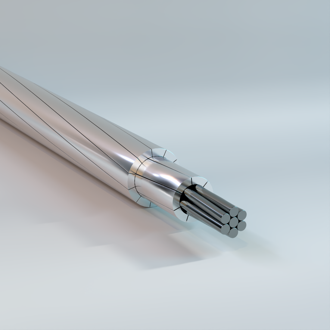
ACSS-TW
Aluminum Conductor, Steel Supported, Bare Overhead Concentric Lay Stranded Conductors, Trapezoidal Wire
Used for overhead power transmission and distribution projects. Trapezoidal shaped wire with compact aluminum concentric-lay-stranded conductor with steel coated core wire(s) makes it a preferred choice due to it’s favorable strength/weight ratio, achieved by the lightweight and good conductivity of aluminum with the high tensile strength of steel. ACSS-TW can be operated up to 250°C whereas the maximum operating temperature of ACSR-TW does not exceed 100°C.
Physical Data
| ACSS-TW | |||||||||||||
|---|---|---|---|---|---|---|---|---|---|---|---|---|---|
| Code Word |
Size AWG or kcmil |
Type | Stranding | Nominal Overall Diameter | Cross Section | Rated Strength | |||||||
| Aluminum | Steel | CDR | Steel Core |
Al | Total | /MA2 | /MA3 | /MA5 | |||||
| No. Al Wires |
No. Al Layers |
No. of Wires |
Diameter | ||||||||||
| in | in | in2 | kip | ||||||||||
| Flicker/ACSS/TW | 477 | 13 | 18 | 2 | 7 | 0.094 | 0.78 | 0.282 | 0.3748 | 0.4234 | 13 | 14.2 | 16.4 |
| Hawk/ACSS/TW | 477 | 16 | 18 | 2 | 7 | 0.1053 | 0.79 | 0.3159 | 0.3745 | 0.4355 | 15.6 | 17.1 | 19.8 |
| Parakeet/ACSS/TW | 556.5 | 13 | 18 | 2 | 7 | 0.1015 | 0.84 | 0.3045 | 0.4372 | 0.4938 | 15.2 | 16.6 | 19.1 |
| Dove/ACSS/TW | 556.5 | 16 | 20 | 2 | 7 | 0.1138 | 0.85 | 0.3414 | 0.4371 | 0.5083 | 18.2 | 19.9 | 23.1 |
| Rook/ACSS/TW | 636 | 13 | 18 | 2 | 7 | 0.1085 | 0.89 | 0.3255 | 0.4994 | 0.5641 | 17.3 | 19 | 21.9 |
| Grosbeak/ACSS/TW | 636 | 16 | 20 | 2 | 7 | 0.1216 | 0.91 | 0.3648 | 0.4996 | 0.5809 | 20.7 | 22.4 | 26 |
| Tern/ACSS/TW | 795 | 7 | 17 | 2 | 7 | 0.0888 | 0.96 | 0.2664 | 0.6247 | 0.668 | 14.2 | 15.2 | 17.5 |
| Puffin/ACSS/TW | 795 | 11 | 21 | 2 | 7 | 0.1108 | 0.98 | 0.3324 | 0.6241 | 0.6916 | 18.9 | 20.6 | 23.7 |
| Condor/ACSS/TW | 795 | 13 | 21 | 2 | 7 | 0.1213 | 0.99 | 0.3639 | 0.6242 | 0.7051 | 21.7 | 23.3 | 26.9 |
| Drake/ACSS/TW | 795 | 16 | 20 | 2 | 7 | 0.136 | 1.01 | 0.408 | 0.6242 | 0.7259 | 25.9 | 28 | 32.5 |
| Phoenix/ACSS/TW | 954 | 5 | 30 | 3 | 7 | 0.0837 | 1.04 | 0.2511 | 0.7497 | 0.7882 | 14.2 | 15.2 | 17.1 |
| Rail/ACSS/TW | 954 | 7 | 32 | 3 | 7 | 0.0971 | 1.06 | 0.2913 | 0.7493 | 0.8011 | 16.7 | 18 | 20.4 |
| Cardinal/ACSS/TW | 954 | 13 | 20 | 2 | 7 | 0.1329 | 1.08 | 0.3987 | 0.7492 | 0.8463 | 26 | 28 | 32.3 |
| Snowbird/ACSS/TW | 1033.5 | 5 | 30 | 3 | 7 | 0.0871 | 1.09 | 0.2613 | 0.8115 | 0.8532 | 15.4 | 16.4 | 18.5 |
| Ortolan/ACSS/TW | 1033.5 | 7 | 33 | 3 | 7 | 0.101 | 1.1 | 0.303 | 0.8112 | 0.8673 | 18.1 | 19.5 | 22 |
| Curlew/ACSS/TW | 1033.5 | 13 | 21 | 2 | 7 | 0.1383 | 1.13 | 0.4149 | 0.8118 | 0.917 | 28.2 | 30.3 | 35 |
| Avocet/ACSS/TW | 1113 | 5 | 30 | 3 | 7 | 0.0904 | 1.13 | 0.2712 | 0.8737 | 0.9186 | 16.3 | 17.5 | 19.5 |
| Bluejay/ACSS/TW | 1113 | 7 | 33 | 3 | 7 | 0.1049 | 1.14 | 0.3147 | 0.8746 | 0.9351 | 19.5 | 21 | 23.8 |
| Finch/ACSS/TW | 1113 | 13 | 39 | 3 | 19 | 0.0862 | 1.18 | 0.431 | 0.8737 | 0.9845 | 30.4 | 33.2 | 38.7 |
| Oxbird/ACSS/TW | 1192.5 | 5 | 30 | 3 | 7 | 0.0936 | 1.17 | 0.2808 | 0.9361 | 0.9843 | 17.5 | 18.7 | 20.9 |
| Bunting/ACSS/TW | 1192.5 | 7 | 33 | 3 | 7 | 0.1086 | 1.18 | 0.3258 | 0.9368 | 1.0016 | 20.9 | 22.5 | 25.5 |
| Grackle/ACSS/TW | 1192.5 | 13 | 39 | 3 | 19 | 0.0892 | 1.22 | 0.446 | 0.9369 | 1.0556 | 32.6 | 35.5 | 41.5 |
| Scissortail/ACSS/TW | 1272 | 5 | 30 | 3 | 7 | 0.0967 | 1.2 | 0.2901 | 0.9994 | 1.0508 | 18.7 | 20 | 22.3 |
| Bittern/ACSS/TW | 1272 | 7 | 33 | 3 | 7 | 0.1121 | 1.22 | 0.3363 | 0.9994 | 1.0685 | 22.3 | 24 | 27.2 |
| Pheasant/ACSS/TW | 1272 | 13 | 39 | 3 | 19 | 0.0921 | 1.26 | 0.4605 | 0.9987 | 1.1252 | 34.1 | 37.3 | 43 |
| Dipper/ACSS/TW | 1351.5 | 7 | 33 | 3 | 7 | 0.1155 | 1.25 | 0.3465 | 1.0616 | 1.135 | 23.7 | 25.5 | 28.8 |
| Martin/ACSS/TW | 1351.5 | 13 | 39 | 3 | 19 | 0.0949 | 1.3 | 0.4745 | 1.061 | 1.1954 | 36.2 | 39.6 | 45.6 |
| Bobolink/ACSS/TW | 1431 | 7 | 33 | 3 | 7 | 0.1189 | 1.29 | 0.3567 | 1.1243 | 1.202 | 25.1 | 27 | 30.5 |
| Plover/ACSS/TW | 1431 | 13 | 39 | 3 | 19 | 0.0977 | 1.33 | 0.4885 | 1.1242 | 1.2666 | 38.4 | 41.9 | 48.3 |
| Lapwing/ACSS/TW | 1590 | 7 | 36 | 3 | 7 | 0.1253 | 1.36 | 0.3759 | 1.2488 | 1.3351 | 27.9 | 29.6 | 33.5 |
| Falcon/ACSS/TW | 1590 | 13 | 39 | 3 | 19 | 0.103 | 1.4 | 0.515 | 1.2483 | 1.4066 | 42.6 | 46.6 | 53.7 |
| Chukar/ACSS/TW | 1780 | 8 | 38 | 3 | 19 | 0.0874 | 1.45 | 0.437 | 1.3982 | 1.5122 | 35.3 | 38.2 | 43.9 |
| Bluebird/ACSS/TW* | 2156 | 8 | 64 | 4 | 19 | 0.0961 | 1.61 | 0.4805 | 1.6934 | 1.8312 | 42.1 | 45.5 | 51.7 |
| 1. Code words shown are for standard ACSS/TW/MA2 conductor. See the options for other applicable code word modifiers. 2. Rated strengths shown are applicable for ACSS/MA2 and ACSS/MA3 cores. 3. Direct current resistance is based on 63% IACS for 1350 wires and 8% IACS for the steel core at 20 °C. 4. Consult IEEE 738 Standard for Calculating the Current-Temperature of Bare Overhead Conductors. 5. The above data are an estimate based on given criteria and subject to normal manufacturing tolerances. |
|||||||||||||
| ACSS-TW (cont.) | |||||||||||||
|---|---|---|---|---|---|---|---|---|---|---|---|---|---|
| Code Word |
Size AWG or kcmil |
Type | Mass | Percent of Total Mass | Resistance | GMR | Reactance | ||||||
| Al | Steel | Total | Al | Steel | dc | ac – 60 Hz | Capacitive | Inductive | |||||
| 20 °C | 25 °C | 75 °C | |||||||||||
| lb/kft | Ω/kft | ft | MΩ/kft | Ω/kft | |||||||||
| Flicker/ACSS/TW | 477 | 13 | 448 | 164 | 612 | 73.14 | 26.86 | 0.0347 | 0.0356 | 0.0428 | 0.0259 | 0.5375 | 0.0839 |
| Hawk/ACSS/TW | 477 | 16 | 448 | 206 | 655 | 68.47 | 31.53 | 0.0346 | 0.0354 | 0.0426 | 0.0266 | 0.5349 | 0.0834 |
| Parakeet/ACSS/TW | 556.5 | 13 | 522 | 192 | 714 | 73.15 | 26.85 | 0.0297 | 0.0305 | 0.0367 | 0.0279 | 0.5259 | 0.0822 |
| Dove/ACSS/TW | 556.5 | 16 | 523 | 241 | 764 | 68.45 | 31.55 | 0.0296 | 0.0304 | 0.0366 | 0.0287 | 0.5232 | 0.0816 |
| Rook/ACSS/TW | 636 | 13 | 597 | 219 | 816 | 73.15 | 26.85 | 0.026 | 0.0268 | 0.0321 | 0.0298 | 0.5159 | 0.0808 |
| Grosbeak/ACSS/TW | 636 | 16 | 598 | 275 | 873 | 68.47 | 31.53 | 0.0259 | 0.0267 | 0.032 | 0.0307 | 0.5129 | 0.0801 |
| Tern/ACSS/TW | 795 | 7 | 745 | 147 | 892 | 83.54 | 16.46 | 0.0209 | 0.0217 | 0.026 | 0.0315 | 0.5042 | 0.0795 |
| Puffin/ACSS/TW | 795 | 11 | 746 | 229 | 974 | 76.55 | 23.45 | 0.0209 | 0.0216 | 0.0259 | 0.0327 | 0.5009 | 0.0786 |
| Condor/ACSS/TW | 795 | 13 | 746 | 274 | 1020 | 73.15 | 26.85 | 0.0208 | 0.0215 | 0.0258 | 0.0333 | 0.4987 | 0.0782 |
| Drake/ACSS/TW | 795 | 16 | 747 | 344 | 1091 | 68.45 | 31.55 | 0.0207 | 0.0214 | 0.0257 | 0.0342 | 0.4962 | 0.0776 |
| Phoenix/ACSS/TW | 954 | 5 | 898 | 130 | 1028 | 87.32 | 12.68 | 0.0176 | 0.0184 | 0.0221 | 0.0343 | 0.491 | 0.0775 |
| Rail/ACSS/TW | 954 | 7 | 899 | 175 | 1074 | 83.66 | 16.34 | 0.0175 | 0.0183 | 0.022 | 0.035 | 0.4889 | 0.0771 |
| Cardinal/ACSS/TW | 954 | 13 | 895 | 329 | 1224 | 73.15 | 26.85 | 0.0173 | 0.018 | 0.0216 | 0.0364 | 0.4851 | 0.0762 |
| Snowbird/ACSS/TW | 1033.5 | 5 | 972 | 141 | 1114 | 87.32 | 12.68 | 0.0162 | 0.017 | 0.0204 | 0.0357 | 0.4844 | 0.0766 |
| Ortolan/ACSS/TW | 1033.5 | 7 | 973 | 190 | 1163 | 83.68 | 16.32 | 0.0162 | 0.017 | 0.0204 | 0.0364 | 0.4829 | 0.0762 |
| Curlew/ACSS/TW | 1033.5 | 13 | 970 | 356 | 1326 | 73.15 | 26.85 | 0.016 | 0.0167 | 0.02 | 0.0379 | 0.4787 | 0.0752 |
| Avocet/ACSS/TW | 1113 | 5 | 1047 | 152 | 1199 | 87.32 | 12.68 | 0.015 | 0.0159 | 0.019 | 0.037 | 0.479 | 0.0758 |
| Bluejay/ACSS/TW | 1113 | 7 | 1048 | 205 | 1253 | 83.66 | 16.34 | 0.015 | 0.0158 | 0.019 | 0.0377 | 0.4772 | 0.0753 |
| Finch/ACSS/TW | 1113 | 13 | 1051 | 376 | 1427 | 73.64 | 26.36 | 0.015 | 0.0156 | 0.0192 | 0.0399 | 0.4716 | 0.074 |
| Oxbird/ACSS/TW | 1192.5 | 5 | 1122 | 163 | 1285 | 87.31 | 12.69 | 0.014 | 0.0149 | 0.0178 | 0.0382 | 0.4738 | 0.075 |
| Bunting/ACSS/TW | 1192.5 | 7 | 1123 | 220 | 1343 | 83.65 | 16.35 | 0.014 | 0.0148 | 0.0178 | 0.039 | 0.472 | 0.0746 |
| Grackle/ACSS/TW | 1192.5 | 13 | 1126 | 403 | 1529 | 73.65 | 26.35 | 0.014 | 0.0147 | 0.0179 | 0.0412 | 0.4665 | 0.0733 |
| Scissortail/ACSS/TW | 1272 | 5 | 1197 | 174 | 1371 | 87.3 | 12.7 | 0.0132 | 0.014 | 0.0168 | 0.0394 | 0.469 | 0.0743 |
| Bittern/ACSS/TW | 1272 | 7 | 1198 | 234 | 1432 | 83.67 | 16.33 | 0.0131 | 0.014 | 0.0167 | 0.0402 | 0.4672 | 0.0739 |
| Pheasant/ACSS/TW | 1272 | 13 | 1201 | 429 | 1630 | 73.66 | 26.34 | 0.0131 | 0.0138 | 0.0169 | 0.0424 | 0.4619 | 0.0726 |
| Dipper/ACSS/TW | 1351.5 | 7 | 1273 | 248 | 1521 | 83.68 | 16.32 | 0.0124 | 0.0132 | 0.0158 | 0.0414 | 0.4626 | 0.0732 |
| Martin/ACSS/TW | 1351.5 | 13 | 1276 | 456 | 1732 | 73.68 | 26.32 | 0.0123 | 0.013 | 0.0159 | 0.0437 | 0.4572 | 0.0719 |
| Bobolink/ACSS/TW | 1431 | 7 | 1348 | 263 | 1611 | 83.67 | 16.33 | 0.0117 | 0.0125 | 0.015 | 0.0427 | 0.4578 | 0.0725 |
| Plover/ACSS/TW | 1431 | 13 | 1351 | 483 | 1834 | 73.66 | 26.34 | 0.0116 | 0.0124 | 0.0151 | 0.045 | 0.4527 | 0.0713 |
| Lapwing/ACSS/TW | 1590 | 7 | 1498 | 292 | 1790 | 83.67 | 16.33 | 0.0105 | 0.0114 | 0.0145 | 0.045 | 0.4495 | 0.0712 |
| Falcon/ACSS/TW | 1590 | 13 | 1501 | 537 | 2038 | 73.65 | 26.35 | 0.0105 | 0.0112 | 0.0163 | 0.0473 | 0.4448 | 0.0701 |
| Chukar/ACSS/TW | 1780 | 8 | 1674 | 387 | 2061 | 81.24 | 18.76 | 0.0094 | 0.0103 | 0.0124 | 0.0482 | 0.4398 | 0.0697 |
| Bluebird/ACSS/TW* | 2156 | 8 | 2045 | 467 | 2512 | 81.39 | 18.61 | 0.0078 | 0.0088 | 0.0103 | 0.0538 | 0.4229 | 0.0672 |
| 1. Code words shown are for standard ACSS/TW/MA2 conductor. See the options for other applicable code word modifiers. 2. Rated strengths shown are applicable for ACSS/MA2 and ACSS/MA3 cores. 3. Direct current resistance is based on 63% IACS for 1350 wires and 8% IACS for the steel core at 20 °C. 4. Consult IEEE 738 Standard for Calculating the Current-Temperature of Bare Overhead Conductors. 5. The above data are an estimate based on given criteria and subject to normal manufacturing tolerances. |
|||||||||||||
| ACSS-TW (cont.) | |||||||||||||
|---|---|---|---|---|---|---|---|---|---|---|---|---|---|
| Code Word |
Size AWG or kcmil |
Type | Stranding | Nominal Overall Diameter | Cross Section | Rated Strength | |||||||
| Aluminum | Steel | CDR | Steel Core |
Aluminum | Total | /MA2 | /MA3 | /MA5 | |||||
| No. Al Wires |
No. Al Layers |
No. of Wires |
Diameter | ||||||||||
| in | in | in2 | kip | ||||||||||
| Mohawk/ACSS/TW | 571.7 | 13 | 18 | 2 | 7 | 0.103 | 0.846 | 0.309 | 0.4489 | 0.5072 | 15.6 | 17.1 | 19.7 |
| Calumet/ACSS/TW | 565.3 | 16 | 20 | 2 | 7 | 0.1146 | 0.858 | 0.3438 | 0.4438 | 0.5161 | 18.4 | 20.2 | 23.5 |
| Mystic/ACSS/TW | 666.6 | 13 | 20 | 2 | 7 | 0.1111 | 0.913 | 0.3333 | 0.5236 | 0.5915 | 18.2 | 19.9 | 22.9 |
| Oswego/ACSS/TW | 664.8 | 16 | 20 | 2 | 7 | 0.1244 | 0.927 | 0.3732 | 0.5222 | 0.6073 | 21.7 | 23.4 | 27.2 |
| Maumee/ACSS/TW | 768.2 | 13 | 20 | 2 | 7 | 0.1195 | 0.977 | 0.3585 | 0.6032 | 0.6817 | 21 | 23 | 26.5 |
| Wabash/ACSS/TW | 762.8 | 16 | 20 | 2 | 7 | 0.1331 | 0.99 | 0.3993 | 0.5989 | 0.6963 | 24.9 | 26.8 | 31.2 |
| Kettle/ACSS/TW | 957.2 | 7 | 32 | 3 | 7 | 0.0973 | 1.06 | 0.2919 | 0.7518 | 0.8038 | 16.8 | 18.1 | 20.4 |
| Suwannee/ACSS/TW | 959.6 | 16 | 22 | 2 | 7 | 0.1493 | 1.108 | 0.4479 | 0.7539 | 0.8764 | 30.7 | 33.1 | 38.6 |
| Cheyenne/ACSS/TW | 1168.1 | 5 | 30 | 3 | 7 | 0.0926 | 1.155 | 0.2778 | 0.917 | 0.9642 | 17.2 | 18.3 | 20.4 |
| Genesee/ACSS/TW | 1158 | 7 | 33 | 3 | 7 | 0.1078 | 1.165 | 0.3234 | 0.9094 | 0.9732 | 20.5 | 22.1 | 25 |
| Hudson/ACSS/TW | 1158.4 | 13 | 26 | 2 | 7 | 0.1467 | 1.196 | 0.4401 | 0.9096 | 1.0279 | 31.1 | 33.5 | 38.8 |
| Catawba/ACSS/TW | 1272 | 5 | 30 | 3 | 7 | 0.0967 | 1.203 | 0.2901 | 0.9993 | 1.0507 | 18.7 | 20 | 22.3 |
| Nelson/ACSS/TW | 1257.1 | 7 | 35 | 3 | 7 | 0.1115 | 1.213 | 0.3345 | 0.9875 | 1.0558 | 22.1 | 23.8 | 26.9 |
| Yukon/ACSS/TW | 1233.6 | 13 | 38 | 3 | 19 | 0.091 | 1.25 | 0.455 | 0.9685 | 1.0921 | 33.2 | 36.3 | 41.9 |
| Truckee/ACSS/TW | 1372.5 | 5 | 30 | 3 | 7 | 0.1004 | 1.248 | 0.3012 | 1.0783 | 1.1337 | 20.2 | 21.5 | 24 |
| Mackenzie/ACSS/TW | 1359.7 | 7 | 36 | 3 | 7 | 0.1159 | 1.259 | 0.3477 | 1.0674 | 1.1413 | 23.9 | 25.7 | 29 |
| Thames/ACSS/TW | 1334.6 | 13 | 39 | 3 | 19 | 0.0944 | 1.29 | 0.472 | 1.0479 | 1.1808 | 35.8 | 39.1 | 45.1 |
| St.Croix/ACSS/TW | 1467.8 | 5 | 30 | 3 | 7 | 0.1041 | 1.292 | 0.3123 | 1.1532 | 1.2127 | 21.6 | 23.1 | 25.8 |
| Miramichi/ACSS/TW | 1455.3 | 7 | 36 | 3 | 7 | 0.12 | 1.299 | 0.36 | 1.1427 | 1.2219 | 25.6 | 27.1 | 30.7 |
| Merrimack/ACSS/TW | 1433.6 | 13 | 44 | 3 | 19 | 0.0978 | 1.34 | 0.489 | 1.1255 | 1.2682 | 38.4 | 42 | 48.4 |
| Platte/ACSS/TW | 1569 | 5 | 33 | 3 | 7 | 0.1074 | 1.334 | 0.3222 | 1.2328 | 1.2962 | 23.1 | 24.6 | 27.5 |
| Potomac/ACSS/TW | 1557.4 | 7 | 36 | 3 | 7 | 0.1241 | 1.345 | 0.3723 | 1.2237 | 1.3084 | 27.3 | 29 | 32.8 |
| Rio Grande/ACSS/TW | 1533.3 | 13 | 39 | 3 | 19 | 0.1012 | 1.379 | 0.506 | 1.2046 | 1.3574 | 41.2 | 45 | 51.9 |
| Schuylkill/ACSS/TW | 1657.4 | 7 | 36 | 3 | 7 | 0.128 | 1.386 | 0.384 | 1.3012 | 1.3912 | 29.1 | 30.9 | 34.9 |
| Pecos/ACSS/TW | 1622 | 13 | 39 | 3 | 19 | 0.1064 | 1.424 | 0.532 | 1.2736 | 1.4425 | 45 | 49.3 | 56.9 |
| Pee Dee/ACSS/TW | 1758.6 | 7 | 37 | 3 | 7 | 0.1319 | 1.431 | 0.3957 | 1.3811 | 1.4768 | 30.9 | 32.8 | 37.1 |
| James/ACSS/TW | 1730.6 | 13 | 39 | 3 | 19 | 0.1075 | 1.47 | 0.5375 | 1.3598 | 1.5322 | 46.4 | 50.8 | 58.5 |
| Athabaska/ACSS/TW | 1949.6 | 7 | 42 | 3 | 7 | 0.1392 | 1.504 | 0.4176 | 1.5318 | 1.6384 | 34.3 | 36.5 | 40.8 |
| Cumberland/ACSS/TW | 1926.9 | 13 | 42 | 3 | 19 | 0.1133 | 1.545 | 0.5665 | 1.5129 | 1.7044 | 51.6 | 56.4 | 65 |
| Santee/ACSS/TW* | 2627.3 | 8 | 64 | 4 | 19 | 0.1062 | 1.762 | 0.531 | 2.0645 | 2.2328 | 51.3 | 55.6 | 63.1 |
| 1. Code words shown are for standard ACSS/TW/MA2 conductor. See the options for other applicable code word modifiers. 2. Rated strengths shown are applicable for ACSS/MA2 and ACSS/MA3 cores. 3. Direct current resistance is based on 63% IACS for 1350 wires and 8% IACS for the steel core at 20 °C. 4. Consult IEEE 738 Standard for Calculating the Current-Temperature of Bare Overhead Conductors. 5. The above data are an estimate based on given criteria and subject to normal manufacturing tolerances. |
|||||||||||||
| ACSS-TW (cont.) | |||||||||||||
|---|---|---|---|---|---|---|---|---|---|---|---|---|---|
| Code Word |
Size AWG or kcmil |
Type | Mass | Percent of Total Mass | Resistance | GMR | Reactance | ||||||
| Al | Steel | Total | Al | Steel | dc | ac – 60 Hz | Capacitive | Inductive | |||||
| 20 °C | 25°C | 75°C | |||||||||||
| lb/kft | Ω/kft | ft | MΩ/kft | Ω/kft | |||||||||
| Mohawk/ACSS/TW | 571.7 | 13 | 537 | 197 | 734 | 73.1 | 26.9 | 0.0298 | 0.0306 | 0.0365 | 0.0283 | 0.5239 | 0.082 |
| Calumet/ACSS/TW | 565.3 | 16 | 531 | 244 | 776 | 68.48 | 31.52 | 0.03 | 0.0308 | 0.0368 | 0.029 | 0.5217 | 0.0814 |
| Mystic/ACSS/TW | 666.6 | 13 | 626 | 230 | 855 | 73.14 | 26.86 | 0.0255 | 0.0263 | 0.0314 | 0.0306 | 0.512 | 0.0801 |
| Oswego/ACSS/TW | 664.8 | 16 | 625 | 288 | 913 | 68.44 | 31.56 | 0.0255 | 0.0262 | 0.0314 | 0.0313 | 0.5096 | 0.0796 |
| Maumee/ACSS/TW | 768.2 | 13 | 721 | 266 | 987 | 73.07 | 26.93 | 0.0222 | 0.0229 | 0.0273 | 0.0328 | 0.5014 | 0.0786 |
| Wabash/ACSS/TW | 762.8 | 16 | 717 | 330 | 1046 | 68.49 | 31.51 | 0.0222 | 0.0229 | 0.0274 | 0.0335 | 0.4993 | 0.0781 |
| Kettle/ACSS/TW | 957.2 | 7 | 902 | 176 | 1078 | 83.65 | 16.35 | 0.018 | 0.0188 | 0.0224 | 0.035 | 0.4886 | 0.077 |
| Suwannee/ACSS/TW | 959.6 | 16 | 902 | 415 | 1317 | 68.49 | 31.51 | 0.0177 | 0.0183 | 0.0218 | 0.0376 | 0.4817 | 0.0754 |
| Cheyenne/ACSS/TW | 1168.1 | 5 | 1099 | 160 | 1259 | 87.32 | 12.68 | 0.0148 | 0.0156 | 0.0186 | 0.0379 | 0.4751 | 0.0752 |
| Genesee/ACSS/TW | 1158 | 7 | 1091 | 216 | 1307 | 83.45 | 16.55 | 0.0149 | 0.0156 | 0.0187 | 0.0385 | 0.4739 | 0.0748 |
| Hudson/ACSS/TW | 1158.4 | 13 | 1087 | 401 | 1488 | 73.08 | 26.92 | 0.0147 | 0.0154 | 0.0183 | 0.0402 | 0.4697 | 0.0738 |
| Catawba/ACSS/TW | 1272 | 5 | 1197 | 174 | 1371 | 87.3 | 12.7 | 0.0136 | 0.0144 | 0.0172 | 0.0395 | 0.4688 | 0.0743 |
| Nelson/ACSS/TW | 1257.1 | 7 | 1184 | 231 | 1415 | 83.65 | 16.35 | 0.0137 | 0.0145 | 0.0172 | 0.0402 | 0.4674 | 0.0739 |
| Yukon/ACSS/TW | 1233.6 | 13 | 1165 | 419 | 1584 | 73.53 | 26.47 | 0.0139 | 0.0146 | 0.0178 | 0.0422 | 0.4628 | 0.0728 |
| Truckee/ACSS/TW | 1372.5 | 5 | 1291 | 188 | 1479 | 87.32 | 12.68 | 0.0126 | 0.0134 | 0.016 | 0.0409 | 0.4631 | 0.0734 |
| Mackenzie/ACSS/TW | 1359.7 | 7 | 1281 | 250 | 1531 | 83.67 | 16.33 | 0.0127 | 0.0135 | 0.016 | 0.0417 | 0.4617 | 0.073 |
| Thames/ACSS/TW | 1334.6 | 13 | 1260 | 451 | 1711 | 73.64 | 26.36 | 0.0128 | 0.0135 | 0.0165 | 0.0435 | 0.4579 | 0.027 |
| St.Croix/ACSS/TW | 1467.8 | 5 | 1381 | 202 | 1583 | 87.26 | 12.74 | 0.0117 | 0.0126 | 0.015 | 0.0424 | 0.4576 | 0.0726 |
| Miramichi/ACSS/TW | 1455.3 | 7 | 1371 | 268 | 1639 | 83.64 | 16.36 | 0.0118 | 0.0127 | 0.015 | 0.043 | 0.4568 | 0.0723 |
| Merrimack/ACSS/TW | 1433.6 | 13 | 1354 | 484 | 1838 | 73.65 | 26.35 | 0.0119 | 0.0127 | 0.0154 | 0.0452 | 0.4519 | 0.0712 |
| Platte/ACSS/TW | 1569 | 5 | 1476 | 215 | 1691 | 87.3 | 12.7 | 0.011 | 0.0119 | 0.0141 | 0.0438 | 0.4527 | 0.0719 |
| Potomac/ACSS/TW | 1557.4 | 7 | 1467 | 287 | 1754 | 83.65 | 16.35 | 0.0111 | 0.0119 | 0.0141 | 0.0445 | 0.4513 | 0.0715 |
| Rio Grande/ACSS/TW | 1533.3 | 13 | 1448 | 518 | 1966 | 73.63 | 26.37 | 0.0112 | 0.0119 | 0.0144 | 0.0466 | 0.4474 | 0.0705 |
| Schuylkill/ACSS/TW | 1657.4 | 7 | 1561 | 305 | 1866 | 83.66 | 16.34 | 0.0104 | 0.0113 | 0.0133 | 0.0459 | 0.4467 | 0.0708 |
| Pecos/ACSS/TW | 1622 | 13 | 1531 | 573 | 2105 | 72.77 | 27.23 | 0.0106 | 0.0113 | 0.0137 | 0.0482 | 0.4424 | 0.0697 |
| Pee Dee/ACSS/TW | 1758.6 | 7 | 1660 | 324 | 1983 | 83.67 | 16.33 | 0.0098 | 0.0107 | 0.0126 | 0.0475 | 0.4416 | 0.07 |
| James/ACSS/TW | 1730.6 | 13 | 1634 | 585 | 2219 | 73.64 | 26.36 | 0.0099 | 0.0107 | 0.0129 | 0.0496 | 0.4374 | 0.069 |
| Athabaska/ACSS/TW | 1949.6 | 7 | 1836 | 361 | 2197 | 83.57 | 16.43 | 0.0088 | 0.0098 | 0.0115 | 0.0499 | 0.4341 | 0.0689 |
| Cumberland/ACSS/TW | 1926.9 | 13 | 1819 | 650 | 2469 | 73.68 | 26.32 | 0.0089 | 0.0097 | 0.0116 | 0.0522 | 0.4296 | 0.0679 |
| Santee/ACSS/TW* | 2627.3 | 8 | 2492 | 571 | 3062 | 81.36 | 18.64 | 0.0066 | 0.0077 | 0.0089 | 0.0589 | 0.409 | 0.0651 |
| 1. Code words shown are for standard ACSS/TW/MA2 conductor. See the options for other applicable code word modifiers. 2. Rated strengths shown are applicable for ACSS/MA2 and ACSS/MA3 cores. 3. Direct current resistance is based on 63% IACS for 1350 wires and 8% IACS for the steel core at 20 °C. 4. Consult IEEE 738 Standard for Calculating the Current-Temperature of Bare Overhead Conductors. 5. The above data are an estimate based on given criteria and subject to normal manufacturing tolerances. |
|||||||||||||
| ACSS-TW Options | ||||
|---|---|---|---|---|
| Steel Coating | Steel Strength | |||
| Standard | High | Extra High | Ultra High | |
| Zinc – 5% Aluminum Mischmetal Alloy Coating | /MA2 /MC2 |
/MA3 | /MA4 | /MA5 |
| /NS: Non-Specular finish available for all ACSS products. /AW: Aluminum-clad steel core – see ACSS/AW catalog sheet. |
||||
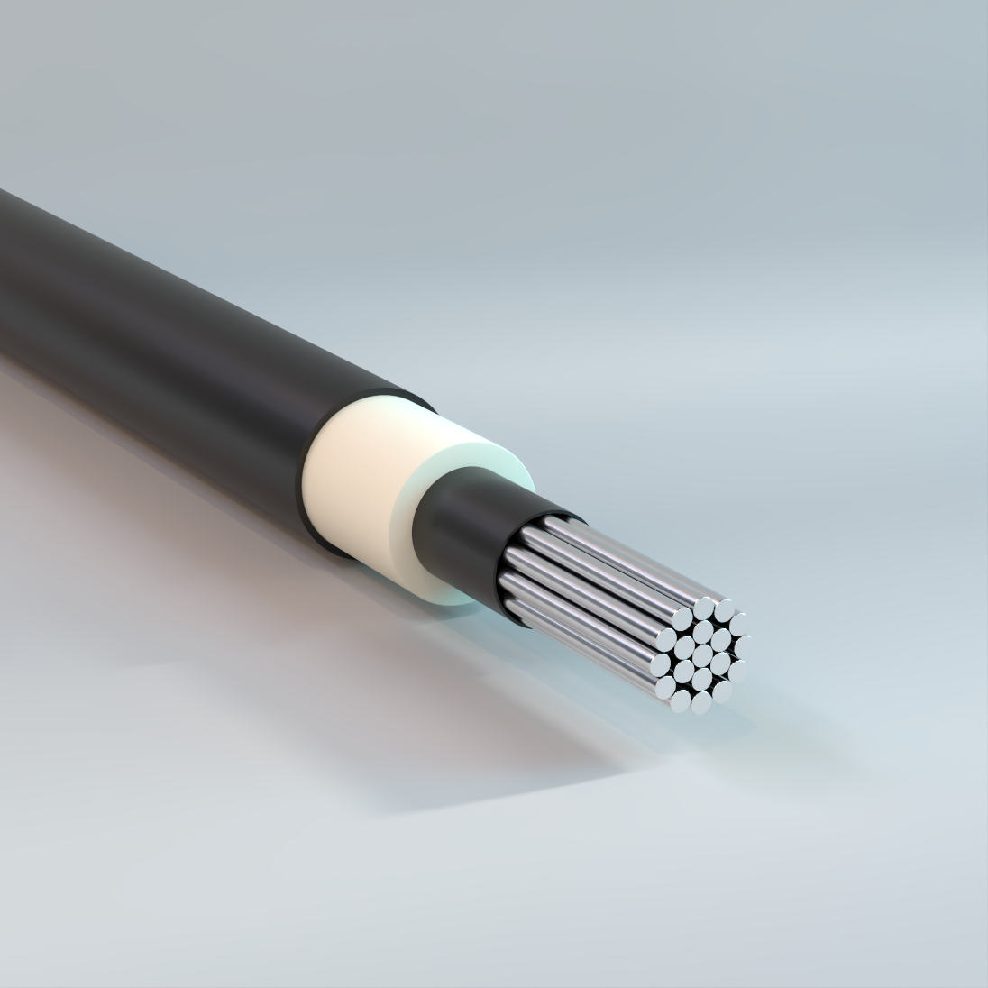
Tree Wire
Overhead, PE or XLPE Insulation, 5kV-35kV – Aluminum
Used for distribution overhead power lines where space for right-of-way is limited or in close proximity to trees and other vegetation.
Physical Data
| AAC Conductor 15 kV System | ||||||||
|---|---|---|---|---|---|---|---|---|
| Size AWG |
Number of Strands |
Conductor Diameter |
Conductor Shield Thickness |
Inner Layer Thickness |
Outer Layer Thickness |
Approximate Outside Diameter |
Approximate Net Weight |
Rated Strength |
| in | mils | mils | mils | in | lb/kft | lbs | ||
| 1/0 | 7 | 0.336 | 15 | 75 | 75 | 694 | 222 | 1791 |
| 2/0 | 7 | 0.376 | 15 | 75 | 75 | 734 | 258 | 2259 |
| 3/0 | 7 | 0.423 | 15 | 75 | 75 | 781 | 303 | 2736 |
| 4/0 | 7 | 0.475 | 15 | 75 | 75 | 833 | 359 | 3447 |
| 266.8 | 19 | 0.537 | 15 | 75 | 75 | 905 | 429 | 4473 |
| 336.4 | 19 | 0.603 | 15 | 75 | 75 | 971 | 513 | 5535 |
| 397.5 | 19 | 0.659 | 15 | 75 | 75 | 1027 | 586 | 6399 |
| 477 | 19 | 0.722 | 15 | 75 | 75 | 1090 | 679 | 7524 |
| 556.5 | 37 | 0.78 | 20 | 75 | 75 | 1148 | 759 | 8946 |
| 636 | 37 | 0.835 | 20 | 75 | 75 | 1213 | 857 | 10260 |
| 795 | 37 | 0.932 | 20 | 80 | 80 | 1330 | 1049 | 12510 |
| The above data are approximate and subject to normal manufacturing tolerances. | ||||||||
| ACSR Conductor 15 kV System | ||||||||
|---|---|---|---|---|---|---|---|---|
| Size AWG |
Number of Strands |
Conductor Diameter |
Conductor Shield Thickness |
Inner Layer Thickness |
Outer Layer Thickness |
Approximate Outside Diameter |
Approximate Net Weight |
Rated Strength |
| in | mils | mils | mils | in | lb/kft | lbs | ||
| 4 | 6/1 | 0. 250 | 15 | 75 | 75 | 608 | 157 | 1767 |
| 2 | 6/1 | 0. 316 | 15 | 75 | 75 | 674 | 208 | 2708 |
| 1/0 | 6/1 | 0. 398 | 15 | 75 | 75 | 756 | 284 | 4161 |
| 2/0 | 6/1 | 0. 447 | 15 | 75 | 75 | 805 | 335 | 5035 |
| 3/0 | 6/1 | 0. 502 | 15 | 75 | 75 | 860 | 399 | 6289 |
| 4/0 | 6/1 | 0. 563 | 15 | 75 | 75 | 921 | 476 | 7933 |
| 266.8 | 18/1 | 0. 609 | 15 | 75 | 75 | 977 | 488 | 6536 |
| 266.8 | 26/7 | 0. 642 | 15 | 75 | 75 | 1010 | 575 | 10735 |
| 336.4 | 18/1 | 0. 684 | 15 | 75 | 75 | 1052 | 585 | 8246 |
| 336.4 | 26/7 | 0. 720 | 15 | 75 | 75 | 1088 | 693 | 13395 |
| 397.5 | 18/1 | 0. 743 | 15 | 75 | 75 | 1111 | 668 | 9443 |
| 397.5 | 24/7 | 0. 772 | 15 | 75 | 75 | 1140 | 757 | 13870 |
| 397.5 | 26/7 | 0. 783 | 15 | 75 | 75 | 1151 | 795 | 15485 |
| 477 | 24/7 | 0. 846 | 15 | 75 | 75 | 1214 | 882 | 16340 |
| 477 | 26/7 | 0. 858 | 15 | 75 | 75 | 1226 | 927 | 18525 |
| 477 | 30/7 | 0. 883 | 15 | 75 | 75 | 1251 | 1025 | 22610 |
| 556.5 | 18/1 | 0. 879 | 20 | 75 | 75 | 1247 | 881 | 13015 |
| 556.5 | 24/7 | 0. 914 | 20 | 75 | 75 | 1282 | 1004 | 18810 |
| 556.5 | 26/7 | 0. 927 | 20 | 75 | 75 | 1295 | 1057 | 21470 |
| 636 | 18/1 | 0. 940 | 20 | 75 | 75 | 1318 | 995 | 14915 |
| 636 | 26/7 | 0. 990 | 20 | 75 | 75 | 1368 | 1196 | 23940 |
| The above data are approximate and subject to normal manufacturing tolerances. | ||||||||
| AAAC Conductor 15 kV System | ||||||||||
|---|---|---|---|---|---|---|---|---|---|---|
| Size | Number of | Conductor Diameter |
Bare AAAC Codename |
ACSR equivalent diameter |
Conductor Shield Thickness |
Inner Layer Thickness |
Outer Layer Thickness |
Approximate Outside Diameter |
Approximate Net Weight |
Rated Strength |
| AWG/Kcmil | in | AWG/Kcmil | mils | mils | mils | in | lb/kft | lbs | ||
| 48.69 | 7 | 0.25 | ALTON | 4 | 15 | 75 | 75 | 608 | 146 | 1584 |
| 77.47 | 7 | 0.316 | AMES | 2 | 15 | 75 | 75 | 674 | 190 | 2520 |
| 123.3 | 7 | 0.398 | AZUSA | 1/0 | 15 | 75 | 75 | 756 | 254 | 3843 |
| 155.4 | 7 | 0.447 | ANAHEIM | 2/0 | 15 | 75 | 75 | 805 | 298 | 4851 |
| 195.7 | 7 | 0.502 | AMHERST | 3/0 | 15 | 75 | 75 | 860 | 351 | 6111 |
| 246.9 | 7 | 0.563 | ALLIANCE | 4/0 | 15 | 75 | 75 | 931 | 423 | 7704 |
| 312.8 | 19 | 0.642 | BUTTE | 266.8 | 15 | 75 | 75 | 1010 | 500 | 9450 |
| 394.5 | 19 | 0.72 | CANTON | 336.4 | 15 | 75 | 75 | 1088 | 599 | 11970 |
| 465.4 | 19 | 0.783 | CAIRO | 397.5 | 15 | 75 | 75 | 1151 | 683 | 14040 |
| 559.5 | 19 | 0.858 | DARIEN | 477 | 20 | 75 | 75 | 1226 | 793 | 16920 |
| 652.4 | 19 | 0.927 | ELGIN | 556.5 | 20 | 75 | 75 | 1305 | 910 | 19710 |
| 740.8 | 37 | 0.99 | FLINT | 636 | 20 | 75 | 75 | 1368 | 994 | 21960 |
| The above data are approximate and subject to normal manufacturing tolerances. | ||||||||||
| AAC Conductor 25 kV System | ||||||||
|---|---|---|---|---|---|---|---|---|
| Size AWG |
Number of Strands |
Conductor Diameter |
Conductor Shield Thickness |
Inner Layer Thickness |
Outer Layer Thickness |
Approximate Outside Diameter |
Approximate Net Weight |
Rated Strength |
| in | mils | mils | mils | in | lb/kft | lbs | ||
| 1/0 | 7 | 0. 336 | 15 | 125 | 125 | 908 | 327 | 1791 |
| 2/0 | 7 | 0. 376 | 15 | 125 | 125 | 948 | 369 | 2259 |
| 3/0 | 7 | 0. 423 | 15 | 125 | 125 | 995 | 420 | 2736 |
| 4/0 | 7 | 0. 475 | 15 | 125 | 125 | 1047 | 483 | 3447 |
| 266.8 | 19 | 0. 537 | 15 | 125 | 125 | 1119 | 563 | 4473 |
| 336.4 | 19 | 0. 603 | 15 | 125 | 125 | 1185 | 655 | 5535 |
| 397.5 | 19 | 0.659 | 15 | 125 | 125 | 1241 | 736 | 6399 |
| 477 | 19 | 0. 722 | 15 | 125 | 125 | 1304 | 837 | 7524 |
| 556.5 | 37 | 0.78 | 20 | 125 | 125 | 1362 | 925 | 8946 |
| 636 | 37 | 0. 835 | 20 | 125 | 125 | 1427 | 1031 | 10260 |
| 795 | 37 | 0. 932 | 20 | 125 | 125 | 1524 | 1220 | 12510 |
| The above data are approximate and subject to normal manufacturing tolerances. | ||||||||
| ACSR Conductor 25 kV System | ||||||||
|---|---|---|---|---|---|---|---|---|
| Size AWG |
Number of Strands |
Conductor Diameter |
Conductor Shield Thickness |
Inner Layer Thickness |
Outer Layer Thickness |
Approximate Outside Diameter |
Approximate Net Weight |
Rated Strength |
| in | mils | mils | mils | in | lb/kft | lbs | ||
| 1/0 | 6/1 | 0. 398 | 15 | 125 | 125 | 970 | 398 | 4161 |
| 2/0 | 6/1 | 0. 447 | 15 | 125 | 125 | 1019 | 456 | 5035 |
| 3/0 | 6/1 | 0. 502 | 15 | 125 | 125 | 1074 | 526 | 6289 |
| 4/0 | 6/1 | 0. 563 | 15 | 125 | 125 | 1135 | 612 | 7933 |
| 266.8 | 18/1 | 0. 609 | 15 | 125 | 125 | 1191 | 631 | 6536 |
| 266.8 | 26/7 | 0. 642 | 15 | 125 | 125 | 1224 | 722 | 10735 |
| 336.4 | 18/1 | 0. 684 | 15 | 125 | 125 | 1266 | 738 | 8246 |
| 336.4 | 26/7 | 0. 720 | 15 | 125 | 125 | 1302 | 851 | 13395 |
| 397.5 | 18/1 | 0. 743 | 15 | 125 | 125 | 1325 | 829 | 9443 |
| 397.5 | 24/7 | 0. 772 | 15 | 125 | 125 | 1354 | 922 | 13870 |
| 397.5 | 26/7 | 0. 783 | 15 | 125 | 125 | 1365 | 961 | 15485 |
| 477 | 24/7 | 0. 846 | 15 | 125 | 125 | 1428 | 1056 | 16340 |
| 477 | 26/7 | 0. 858 | 15 | 125 | 125 | 1440 | 1103 | 18525 |
| 477 | 30/7 | 0. 883 | 15 | 125 | 125 | 1465 | 1204 | 22610 |
| 556.5 | 18/1 | 0. 879 | 20 | 125 | 125 | 1461 | 1060 | 13015 |
| 556.5 | 24/7 | 0. 914 | 20 | 125 | 125 | 1496 | 1188 | 18810 |
| 556.5 | 26/7 | 0. 927 | 20 | 125 | 125 | 1509 | 1243 | 21470 |
| The above data are approximate and subject to normal manufacturing tolerances. | ||||||||
| AAAC Conductor 25 kV System | ||||||||||
|---|---|---|---|---|---|---|---|---|---|---|
| Size | Number of Strands |
Conductor Diameter |
Bare AAAC Codename |
ACSR equivalent diameter |
Conductor Shield Thickness |
Inner Layer Thickness |
Outer Layer Thickness |
Approximate Outside Diameter |
Approximate Net Weight |
Rated Strength |
| AWG/Kcmil | in | AWG/Kcmil | mils | mils | mils | in | lb/kft | lbs | ||
| 77.47 | 7 | 0.316 | AMES | 2 | 15 | 125 | 125 | 888 | 293 | 2520 |
| 123.3 | 7 | 0.398 | AZUSA | 1/0 | 15 | 125 | 125 | 970 | 368 | 3843 |
| 155.4 | 7 | 0.447 | ANAHEIM | 2/0 | 15 | 125 | 125 | 1019 | 418 | 4851 |
| 195.7 | 7 | 0.502 | AMHERST | 3/0 | 15 | 125 | 125 | 1074 | 479 | 6111 |
| 246.9 | 7 | 0.563 | ALLIANCE | 4/0 | 15 | 125 | 125 | 1145 | 560 | 7704 |
| 312.8 | 19 | 0.642 | BUTTE | 266.8 | 15 | 125 | 125 | 1224 | 648 | 9450 |
| 394.5 | 19 | 0.72 | CANTON | 336.4 | 15 | 125 | 125 | 1302 | 757 | 11970 |
| 465.4 | 19 | 0.783 | CAIRO | 397.5 | 15 | 125 | 125 | 1365 | 850 | 14040 |
| 559.5 | 19 | 0.858 | DARIEN | 477 | 20 | 125 | 125 | 1440 | 970 | 16920 |
| 652.4 | 19 | 0.927 | ELGIN | 556.5 | 20 | 125 | 125 | 1519 | 1097 | 19710 |
| 740.8 | 37 | 0.99 | FLINT | 636 | 20 | 125 | 125 | 1582 | 1190 | 21960 |
| The above data are approximate and subject to normal manufacturing tolerances. | ||||||||||
| AAC Conductor 35kV System | ||||||||
|---|---|---|---|---|---|---|---|---|
| Size AWG |
Number of Strands |
Conductor Diameter |
Conductor Shield Thickness |
Inner Layer Thickness |
Outer Layer Thickness |
Approximate Outside Diameter |
Approximate Net Weight |
Rated Strength |
| in | mils | mils | mils | in | lb/kft | lbs | ||
| 1/0 | 7 | 0.336 | 15 | 175 | 125 | 1014 | 391 | 1791 |
| 2/0 | 7 | 0. 376 | 15 | 175 | 125 | 1054 | 436 | 2259 |
| 3/0 | 7 | 0. 423 | 15 | 175 | 125 | 1101 | 491 | 2736 |
| 4/0 | 7 | 0. 475 | 15 | 175 | 125 | 1153 | 557 | 3447 |
| 266.8 | 19 | 0. 537 | 15 | 175 | 125 | 1215 | 641 | 4473 |
| 336.4 | 19 | 0. 603 | 15 | 175 | 125 | 1281 | 738 | 5535 |
| 397.5 | 19 | 0.659 | 15 | 175 | 125 | 1347 | 823 | 6399 |
| 477 | 19 | 0. 722 | 15 | 175 | 125 | 1410 | 928 | 7524 |
| 556.5 | 37 | 0.78 | 20 | 175 | 125 | 1468 | 1020 | 8946 |
| 636 | 37 | 0. 835 | 20 | 175 | 125 | 1523 | 1131 | 10260 |
| 795 | 37 | 0. 932 | 20 | 175 | 125 | 1620 | 1326 | 12510 |
| The above data are approximate and subject to normal manufacturing tolerances. | ||||||||
| ACSR Conductor 35 kV System | ||||||||
|---|---|---|---|---|---|---|---|---|
| Size AWG |
Number of Strands |
Conductor Diameter |
Conductor Shield Thickness |
Inner Layer Thickness |
Outer Layer Thickness |
Approximate Outside Diameter |
Approximate Net Weight |
Rated Strength |
| in | mils | mils | mils | in | lb/kft | lbs | ||
| 1/0 | 6/1 | 0.398 | 15 | 175 | 125 | 1076 | 467 | 4161 |
| 2/0 | 6/1 | 0. 447 | 15 | 175 | 125 | 1125 | 528 | 5035 |
| 3/0 | 6/1 | 0. 502 | 15 | 175 | 125 | 1180 | 602 | 6289 |
| 4/0 | 6/1 | 0. 563 | 15 | 175 | 125 | 1241 | 692 | 7933 |
| 266.8 | 26/7 | 0. 642 | 15 | 175 | 125 | 1320 | 808 | 10735 |
| 336.4 | 18/1 | 0. 684 | 15 | 175 | 125 | 1362 | 827 | 8246 |
| 336.4 | 26/7 | 0. 720 | 15 | 175 | 125 | 1398 | 942 | 13395 |
| 397.5 | 18/1 | 0. 743 | 15 | 175 | 125 | 1431 | 922 | 9443 |
| 397.5 | 24/7 | 0. 772 | 15 | 175 | 125 | 1450 | 1017 | 13870 |
| 397.5 | 26/7 | 0. 783 | 15 | 175 | 125 | 1461 | 1057 | 15485 |
| 477 | 24/7 | 0. 846 | 15 | 175 | 125 | 1534 | 1156 | 16340 |
| 477 | 26/7 | 0. 858 | 15 | 175 | 125 | 1546 | 1204 | 18525 |
| 477 | 30/7 | 0. 883 | 15 | 175 | 125 | 1571 | 1307 | 22610 |
| 556.5 | 18/1 | 0. 879 | 20 | 175 | 125 | 1567 | 1162 | 13015 |
| 556.5 | 24/7 | 0. 914 | 20 | 175 | 125 | 1602 | 1292 | 18810 |
| 556.5 | 26/7 | 0. 927 | 20 | 175 | 125 | 1615 | 1348 | 21470 |
| 636 | 18/1 | 0. 940 | 20 | 175 | 125 | 1628 | 1290 | 14915 |
| 636 | 26/7 | 0. 990 | 20 | 175 | 125 | 1678 | 1501 | 23940 |
| 795 | 26/7 | 0. 1107 | 20 | 175 | 125 | 1795 | 1781 | 29925 |
| 795 | 45/7 | 0. 1063 | 20 | 175 | 125 | 1751 | 1559 | 20995 |
| The above data are approximate and subject to normal manufacturing tolerances. | ||||||||
| AAAC Conductor 35kV System | ||||||||||
|---|---|---|---|---|---|---|---|---|---|---|
| Size | Number of Strands |
Conductor Diameter |
Bare AAAC Codename |
ACSR equivalent diameter |
Conductor Shield Thickness |
Inner Layer Thickness |
Outer Layer Thickness |
Approximate Outside Diameter |
Approximate Net Weight |
Rated Strength |
| AWG/Kcmil | in | AWG/Kcmil | mils | mils | mils | in | lb/kft | lbs | ||
| 123.3 | 7 | 0.398 | AZUSA | 1/0 | 15 | 175 | 125 | 1076 | 436 | 3843 |
| 155.4 | 7 | 0.447 | ANAHEIM | 2/0 | 15 | 175 | 125 | 1125 | 490 | 4851 |
| 195.7 | 7 | 0.502 | AMHERST | 3/0 | 15 | 175 | 125 | 1180 | 554 | 6111 |
| 246.9 | 7 | 0.563 | ALLIANCE | 4/0 | 15 | 175 | 125 | 1251 | 640 | 7704 |
| 312.8 | 19 | 0.642 | BUTTE | 266.8 | 15 | 175 | 125 | 1330 | 733 | 9450 |
| 394.5 | 19 | 0.72 | CANTON | 336.4 | 15 | 175 | 125 | 1408 | 847 | 11970 |
| 465.4 | 19 | 0.783 | CAIRO | 397.5 | 15 | 175 | 125 | 1471 | 945 | 14040 |
| 559.5 | 19 | 0.858 | DARIEN | 477 | 20 | 175 | 125 | 1546 | 1070 | 16920 |
| 652.4 | 19 | 0.927 | ELGIN | 556.5 | 20 | 175 | 125 | 1625 | 1202 | 19710 |
| 740.8 | 37 | 0.99 | FLINT | 636 | 20 | 175 | 125 | 1688 | 1299 | 21960 |
| The above data are approximate and subject to normal manufacturing tolerances. | ||||||||||
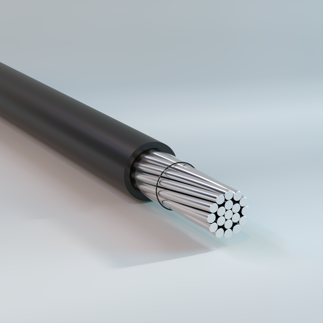
Covered Line Wire
Overhead, ACSR/AAC/AAAC, PE or XLPE Insulation – Aluminum
Used for primary for the distribution of electrical energy under normal condition of overhead (aerial) installation and service outdoors.
Physical Data
| Covered Line Wire ACSR | |||||||
|---|---|---|---|---|---|---|---|
| Code Word |
Size AWG or kcmil |
Number of Strands |
Insulation Thickness |
Cable OD |
Rated Strength |
Weight | |
| PE | XLPE | ||||||
| mil | in | lb | lb/kit | lb/kit | |||
| Walnut | 6 | 6/1 | 30 | 0.25 | 1131 | 47 | 46 |
| Butternut | 4 | 6/1 | 30 | 0.3 | 1767 | 71 | 70 |
| Hickory | 4 | 7/1 | 30 | 0.32 | 2242 | 82 | 82 |
| Pignut | 2 | 6/1 | 45 | 0.39 | 2708 | 116 | 115 |
| Beech | 2 | 7/1 | 45 | 0.42 | 3458 | 135 | 134 |
| Almond | 1/0 | 6/1 | 60 | 0.5 | 4161 | 188 | 186 |
| Pecan | 2/0 | 6/1 | 60 | 0.55 | 5035 | 232 | 229 |
| Cottonwood | 2/0 | 6/1 | 80 | 0.59 | 5035 | 247 | 244 |
| Filbert | 3/0 | 6/1 | 60 | 0.6 | 6289 | 286 | 283 |
| Chokeberry | 3/0 | 6/1 | 80 | 0.64 | 6289 | 303 | 300 |
| Buckeye | 4/0 | 6/1 | 60 | 0.65 | 7933 | 353 | 351 |
| Gumwood | 4/0 | 6/1 | 80 | 0.7 | 7933 | 372 | 369 |
| Hackberry | 266.8 | 18/1 | 60 | 0.72 | 6536 | 356 | 353 |
| Redbud | 266.8 | 18/1 | 80 | 0.76 | 6536 | 377 | 373 |
| Mockernut | 336.4 | 18/1 | 60 | 0.79 | 8246 | 441 | 438 |
| Aspen | 336.4 | 18/1 | 80 | 0.83 | 8246 | 464 | 460 |
| The above data are approximate and subject to normal manufacturing tolerances. Where required, the compatibility with glands, connectors and accessories should be verified using actual dimensions of the product. Other sizes available upon request. | |||||||
| Covered Line Wire AAC | |||||||
|---|---|---|---|---|---|---|---|
| Code Word |
Size AWG or kcmil |
Number of Strands |
Insulation Thickness |
Cable OD |
Rated Strength |
Weight | |
| PE | XLPE | ||||||
| mil | in | lb | lb/kft | lb/kft | |||
| Apple | 6 | 1 | 30 | 0.23 | 445 | 32 | 32 |
| Plum | 6 | 7 | 30 | 0.25 | 535 | 35 | 35 |
| Pear | 4 | 1 | 30 | 0.27 | 710 | 48 | 48 |
| Apricot | 4 | 7 | 30 | 0.3 | 837 | 52 | 52 |
| (No Code) | 4 | 7 | 60 | 0.36 | 837 | 66 | 65 |
| Cherry | 2 | 1 | 45 | 0.35 | 1100 | 80 | 80 |
| Peach | 2 | 7 | 45 | 0.39 | 1283 | 87 | 86 |
| Nectarine | 1 | 7 | 45 | 0.42 | 1558 | 107 | 106 |
| Quince | 1/0 | 7 | 60 | 0.49 | 1891 | 140 | 139 |
| Orange | 2/0 | 7 | 60 | 0.54 | 2385 | 171 | 170 |
| Fig | 3/0 | 7 | 60 | 0.59 | 2888 | 210 | 208 |
| Lemon | 3/0 | 19 | 60 | 0.6 | 2888 | 207 | 206 |
| Olive | 4/0 | 7 | 60 | 0.65 | 3639 | 258 | 256 |
| Pomegranate | 4/0 | 19 | 60 | 0.65 | 3639 | 254 | 253 |
| Sassafras | 250 | 19 | 60 | 0.68 | 4427 | 295 | 294 |
| Catalpa | 250 | 19 | 80 | 0.73 | 4427 | 315 | 313 |
| Mulberry | 266.8 | 19 | 60 | 0.72 | 4589 | 316 | 314 |
| Sycamore | 300 | 19 | 80 | 0.78 | 5206 | 370 | 367 |
| Annona | 336.4 | 19 | 60 | 0.79 | 5843 | 388 | 386 |
| Chinquapin | 350 | 19 | 60 | 0.81 | 6071 | 407 | 409 |
| Ginkgo | 350 | 19 | 80 | 0.85 | 6071 | 427 | 425 |
| Molles | 397.5 | 19 | 80 | 0.89 | 6755 | 477 | 474 |
| Sumac | 450 | 37 | 80 | 0.94 | 7496 | 525 | 522 |
| Huckleberry | 477 | 37 | 80 | 0.96 | 8256 | 552 | 549 |
| Tupelo | 500 | 37 | 80 | 0.98 | 8322 | 578 | 576 |
| Paw Paw | 556.5 | 37 | 80 | 1.02 | 9443 | 637 | 634 |
| Tangerine | 636 | 37 | 95 | 1.12 | 10830 | 736 | 732 |
| Breadfruit | 636 | 61 | 95 | 1.12 | 10830 | 736 | 732 |
| Persimmon | 795 | 61 | 95 | 1.23 | 13585 | 903 | 900 |
| The above data are approximate and subject to normal manufacturing tolerances. Where required, the compatibility with glands, connectors and accessories should be verified using actual dimensions of the product. Other sizes available upon request. | |||||||
| Covered Line Wire AAAC | |||||||
|---|---|---|---|---|---|---|---|
| Code Word |
Size AWG or kcmil | Number of Strands |
Insulation Thickness |
Cable OD |
Rated Strength |
Weight | |
| PE | XLPE | ||||||
| mil | in | lb | lb/kft | lb/kft | |||
| Hornbeam | 4 | 7 | 30 | 0.31 | 1672 | 60 | 60 |
| Linden | 2 | 7 | 45 | 0.41 | 2660 | 100 | 99 |
| Oilnut | 1/0 | 7 | 60 | 0.52 | 4057 | 161 | 160 |
| Waterash | 2/0 | 7 | 60 | 0.6 | 5121 | 201 | 200 |
| Shellbark | 3/0 | 7 | 60 | 0.63 | 6451 | 242 | 241 |
| Planetree | 4/0 | 7 | 60 | 0.69 | 8132 | 298 | 297 |
| The above data are approximate and subject to normal manufacturing tolerances. Where required, the compatibility with glands, connectors and accessories should be verified using actual dimensions of the product. Other sizes available upon request. | |||||||
Ampacity Data
| Covered Line Wire | |
|---|---|
| Conductor Size AWG/kcmil |
Ampacity |
| 8 | 80 |
| 6 | 101 |
| 4 | 127 |
| 2 | 171 |
| 1/0 | 231 |
| 2/0 | 268 |
| 3/0 | 312 |
| 4/0 | 364 |
| 266.8 | 423 |
| 336.4 | 492 |
| 397.5 | 548 |
| 477 | 617 |
| 556.5 | 682 |
| 636 | 744 |
| 795 | 860 |
| 1033.5 | 1017 |
| 1272 | 1201 |
| 1590 | 1381 |
| 2000 | 1527 |
| NEC Table 310.15(B)(21) (formerly Table 310.21) Ampacities of Bare or Covered Conductors in Free Air, Based on 40 °C (104 °F) Ambient, 80 °C (176 °F) Total Conductor Temperature, 610 mm/s (2 ft/s) Wind Velocity. | |
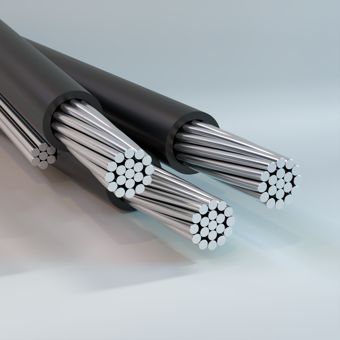
Service Drop
Overhead, Duplex/Triplex/Quadruplex, PE or XLPE Insulation – Aluminum
Used for overhead distribution of electrical energy, such as a supply power, from pole-mounted transformer to the user’s service head where connection to the service entrance cable is made. Also used for temporary services and street light installations.
Physical Data
| Duplex | |||||||||
|---|---|---|---|---|---|---|---|---|---|
| Code Word |
Phase Conductor | Cable OD | Neutral Messenger | Weight | |||||
| Size AWG or kcmil |
Number of Strands |
Insulation Thickness |
in | Size AWG or kcmil |
Number of Strands |
Rated Strength | PE | XLPE | |
| mil | lb | lb/kft | lb/kft | ||||||
| AAC Conductor and Neutral Messenger | |||||||||
| Pekingese | 6 | 1 | 45 | 0.26 | 6 | 7 | 563 | 63 | 63 |
| Collie | 6 | 7 | 45 | 0.28 | 6 | 7 | 563 | 66 | 66 |
| Cocker | 6 | 7 | 60 | 0.31 | 6 | 7 | 563 | 73 | 72 |
| Dachshund | 4 | 1 | 45 | 0.3 | 4 | 7 | 881 | 94 | 94 |
| Spaniel | 4 | 7 | 45 | 0.33 | 4 | 7 | 881 | 99 | 99 |
| Cairn | 4 | 7 | 60 | 0.36 | 4 | 7 | 881 | 106 | 106 |
| Doberman | 2 | 7 | 45 | 0.39 | 2 | 7 | 1350 | 151 | 151 |
| Malemute | 1/0 | 19 | 60 | 0.5 | 1/0 | 7 | 1990 | 241 | 240 |
| The above data are approximate and subject to normal manufacturing tolerances. Where required, the compatibility with glands, connectors and accessories should be verified using actual dimensions of the product. Other sizes available upon request. | |||||||||
| Duplex (cont.) | |||||||||
|---|---|---|---|---|---|---|---|---|---|
| Code Word |
Phase Conductor | Cable OD | Neutral Messenger | Weight | |||||
| Size AWG or kcmil |
Number of Strands |
Insulation Thickness |
in | Size AWG or kcmil |
Number of Strands |
Rated Strength | PE | XLPE | |
| mil | lb | lb/kft | lb/kft | ||||||
| AAC Conductor and ACSR Neutral Messenger | |||||||||
| Setter | 6 | 1 | 45 | 0.26 | 6 | 6/1 | 1190 | 75 | 74 |
| Shepherd | 6 | 7 | 45 | 0.28 | 6 | 6/1 | 1190 | 78 | 78 |
| Retriever | 6 | 7 | 60 | 0.31 | 6 | 6/1 | 1190 | 84 | 84 |
| Eskimo | 4 | 1 | 45 | 0.3 | 4 | 6/1 | 1860 | 113 | 113 |
| Terrier | 4 | 7 | 45 | 0.33 | 4 | 6/1 | 1860 | 118 | 118 |
| Yorkshire | 4 | 7 | 60 | 0.36 | 4 | 6/1 | 1860 | 125 | 125 |
| Chow | 2 | 7 | 45 | 0.39 | 2 | 6/1 | 2850 | 182 | 181 |
| Bull | 1/0 | 19 | 60 | 0.5 | 1/0 | 6/1 | 4380 | 289 | 288 |
| AAC Conductor and AAAC Neutral Messenger | |||||||||
| Chihuahua | 6 | 1 | 45 | 0.26 | 6 | 7 | 1110 | 67 | 67 |
| Vizsla | 6 | 7 | 45 | 0.28 | 6 | 7 | 1110 | 71 | 70 |
| Harrier | 4 | 1 | 45 | 0.3 | 4 | 7 | 1760 | 102 | 101 |
| Whippet | 4 | 7 | 45 | 0.33 | 4 | 7 | 1760 | 106 | 106 |
| Schnauzer | 2 | 7 | 45 | 0.39 | 2 | 7 | 2800 | 163 | 162 |
| Afghan | 1/0 | 7 | 60 | 0.5 | 1/0 | 7 | 4270 | 261 | 260 |
| Heeler | 1/0 | 19 | 60 | 0.5 | 1/0 | 7 | 4270 | 259 | 258 |
| The above data are approximate and subject to normal manufacturing tolerances. Where required, the compatibility with glands, connectors and accessories should be verified using actual dimensions of the product. Other sizes available upon request. | |||||||||
| Triplex | |||||||||
|---|---|---|---|---|---|---|---|---|---|
| Code Word |
Phase Conductor | Cable OD | Neutral Messenger | Weight | |||||
| Size AWG or kcmil |
Number of Strands |
Insulation Thickness |
in | Size AWG or kcmil |
Number of Strands |
Rated Strength | PE | XLPE | |
| mil | lb | lb/kft | lb/kft | ||||||
| AAC Conductor and Neutral Messenger | |||||||||
| Haliotis | 6 | 1 | 45 | 0.26 | 6 | 7 | 563 | 101 | 100 |
| Patella | 6 | 7 | 45 | 0.28 | 6 | 7 | 563 | 108 | 107 |
| Fusus | 4 | 1 | 45 | 0.3 | 4 | 7 | 881 | 149 | 149 |
| Oyster | 4 | 7 | 45 | 0.33 | 4 | 7 | 881 | 159 | 158 |
| Clam | 2 | 7 | 45 | 0.39 | 2 | 7 | 1350 | 240 | 238 |
| Snail | 1/0 | 7 | 60 | 0.5 | 2 | 7 | 1350 | 387 | 385 |
| Murex | 1/0 | 7 | 60 | 0.5 | 1/0 | 7 | 1990 | 387 | 385 |
| Purpura | 1/0 | 19 | 60 | 0.5 | 1/0 | 7 | 1990 | 382 | 380 |
| Nassa | 2/0 | 7 | 60 | 0.55 | 2/0 | 7 | 2510 | 477 | 474 |
| Trophon | 2/0 | 19 | 60 | 0.55 | 2/0 | 7 | 2510 | 471 | 469 |
| Melita | 3/0 | 19 | 60 | 0.6 | 3/0 | 19 | 3040 | 581 | 579 |
| Portunus | 4/0 | 19 | 60 | 0.65 | 4/0 | 19 | 3830 | 721 | 718 |
| Nannynose | 336.4 | 19 | 80 | 0.83 | 336.4 | 19 | 6150 | 1162 | 1157 |
| The above data are approximate and subject to normal manufacturing tolerances. Where required, the compatibility with glands, connectors and accessories should be verified using actual dimensions of the product. Other sizes available upon request. | |||||||||
| Triplex (cont.) | |||||||||
|---|---|---|---|---|---|---|---|---|---|
| Code Word |
Phase Conductor | Cable OD | Neutral Messenger | Weight | |||||
| Size AWG or kcmil |
Number of Strands |
Insulation Thickness |
in | Size AWG or kcmil |
Number of Strands |
Rated Strength | PE | XLPE | |
| mil | lb | lb/kft | lb/kft | ||||||
| AAC Conductor and ACSR Neutral Messenger | |||||||||
| Paludina | 6 | 1 | 45 | 0.26 | 6 | 6/1 | 1190 | 112 | 112 |
| Voluta | 6 | 7 | 45 | 0.28 | 6 | 6/1 | 1190 | 119 | 119 |
| Bolma | 6 | 7 | 60 | 0.31 | 6 | 6/1 | 1190 | 132 | 131 |
| Scallop | 4 | 1 | 45 | 0.3 | 6 | 6/1 | 1190 | 147 | 146 |
| Strombus | 4 | 7 | 45 | 0.33 | 6 | 6/1 | 1190 | 156 | 155 |
| Whelk | 4 | 1 | 45 | 0.3 | 4 | 6/1 | 1860 | 168 | 168 |
| Periwinkle | 4 | 7 | 45 | 0.33 | 4 | 6/1 | 1860 | 178 | 177 |
| Calma | 4 | 7 | 60 | 0.36 | 4 | 6/1 | 1860 | 192 | 191 |
| Cockle | 2 | 7 | 45 | 0.39 | 4 | 6/1 | 1860 | 235 | 234 |
| Conch | 2 | 7 | 45 | 0.39 | 2 | 6/1 | 2850 | 270 | 269 |
| Gebia | 2 | 7 | 60 | 0.42 | 4 | 6/1 | 1860 | 252 | 250 |
| Janthina | 1/0 | 7 | 60 | 0.5 | 2 | 6/1 | 2850 | 380 | 378 |
| Ranella | 1/0 | 19 | 60 | 0.5 | 2 | 6/1 | 2850 | 375 | 373 |
| Neritina | 1/0 | 7 | 60 | 0.5 | 1/0 | 6/1 | 4380 | 435 | 433 |
| Cenia | 1/0 | 19 | 60 | 0.5 | 1/0 | 6/1 | 4380 | 430 | 428 |
| Cavolinia | 2/0 | 7 | 60 | 0.55 | 1 | 6/1 | 3550 | 468 | 465 |
| Clio | 2/0 | 19 | 60 | 0.55 | 1 | 6/1 | 3550 | 462 | 460 |
| Runcina | 2/0 | 7 | 60 | 0.55 | 2/0 | 6/1 | 5300 | 537 | 535 |
| Triton | 2/0 | 19 | 60 | 0.55 | 2/0 | 6/1 | 5300 | 531 | 529 |
| Aega | 3/0 | 19 | 60 | 0.6 | 1/0 | 6/1 | 4380 | 570 | 568 |
| Mursia | 3/0 | 19 | 60 | 0.6 | 3/0 | 6/1 | 6620 | 658 | 655 |
| Cerapus | 4/0 | 19 | 60 | 0.65 | 2/0 | 6/1 | 5300 | 705 | 702 |
| Zuzara | 4/0 | 19 | 60 | 0.65 | 4/0 | 6/1 | 8350 | 815 | 813 |
| Dosinia | 266.8 | 19 | 80 | 0.76 | 266.8 | 18/1 | 6880 | 982 | 977 |
| Cowry | 336.4 | 19 | 80 | 0.83 | 4/0 | 6/1 | 8350 | 1137 | 1132 |
| Limpet | 336.4 | 19 | 80 | 0.83 | 336.4 | 18/1 | 8680 | 1213 | 1208 |
| AAC Conductor and AAAC Neutral Messenger | |||||||||
| Minex | 6 | 1 | 45 | 0.26 | 6 | 7 | 1110 | 105 | 104 |
| Hippa | 6 | 7 | 45 | 0.28 | 6 | 7 | 1110 | 112 | 111 |
| Artemia | 4 | 1 | 45 | 0.3 | 6 | 7 | 1110 | 139 | 138 |
| Crab | 4 | 1 | 45 | 0.33 | 6 | 7 | 1110 | 143 | 142 |
| Prawn | 4 | 1 | 45 | 0.3 | 4 | 7 | 1760 | 156 | 156 |
| Barnacles | 4 | 7 | 45 | 0.33 | 4 | 7 | 1760 | 166 | 165 |
| Solaster | 2 | 7 | 45 | 0.39 | 4 | 7 | 1760 | 223 | 222 |
| Shrimp | 2 | 7 | 45 | 0.39 | 2 | 7 | 2800 | 251 | 250 |
| Lobster | 2 | 7 | 60 | 0.42 | 2 | 7 | 2800 | 268 | 266 |
| Sandcrab | 1/0 | 7 | 60 | 0.5 | 2 | 7 | 2800 | 361 | 359 |
| Echinus | 1/0 | 19 | 60 | 0.5 | 2 | 7 | 2800 | 356 | 354 |
| Gammarus | 1/0 | 7 | 60 | 0.5 | 1/0 | 7 | 4270 | 405 | 403 |
| Leda | 1/0 | 19 | 60 | 0.5 | 1/0 | 7 | 4270 | 400 | 398 |
| Dungeness | 2/0 | 7 | 60 | 0.55 | 2/0 | 7 | 5390 | 499 | 497 |
| Cyclops | 2/0 | 19 | 60 | 0.55 | 2/0 | 7 | 5390 | 493 | 497 |
| Fulgur | 3/0 | 19 | 60 | 0.6 | 1/0 | 7 | 4270 | 540 | 537 |
| Flustra | 3/0 | 19 | 60 | 0.6 | 3/0 | 7 | 6790 | 609 | 607 |
| Arca | 4/0 | 19 | 60 | 0.65 | 2/0 | 7 | 5390 | 667 | 665 |
| Lepas | 4/0 | 19 | 60 | 0.65 | 4/0 | 7 | 8560 | 755 | 752 |
| The above data are approximate and subject to normal manufacturing tolerances. Where required, the compatibility with glands, connectors and accessories should be verified using actual dimensions of the product. Other sizes available upon request. | |||||||||
| Quadruplex | |||||||||
|---|---|---|---|---|---|---|---|---|---|
| Code Word |
Phase Conductor | Cable OD | Neutral Messenger | Weight | |||||
| Size AWG or kcmil |
Number of Strands |
Insulation Thickness |
in | Size AWG or kcmil |
Number of Strands |
Rated Strength | PE | XLPE | |
| mil | lb | lb/kft | lb/kft | ||||||
| AAC Conductor and Neutral Messenger | |||||||||
| Quarter | 6 | 1 | 45 | 0.26 | 6 | 7 | 563 | 138 | 137 |
| Clydesdale | 4 | 1 | 45 | 0.3 | 4 | 7 | 881 | 204 | 203 |
| Pinto | 4 | 7 | 45 | 0.33 | 4 | 7 | 881 | 219 | 217 |
| Mustang | 2 | 7 | 45 | 0.39 | 2 | 7 | 1350 | 328 | 326 |
| Criollo | 1/0 | 19 | 60 | 0.5 | 1/0 | 7 | 1990 | 524 | 520 |
| Percheron | 2/0 | 19 | 60 | 0.55 | 2/0 | 7 | 2510 | 643 | 640 |
| Hanoverian | 3/0 | 19 | 60 | 0.6 | 3/0 | 19 | 3040 | 792 | 788 |
| Singlefoot | 4/0 | 7 | 60 | 0.65 | 4/0 | 19 | 3830 | 993 | 988 |
| Oldenburg | 4/0 | 19 | 60 | 0.65 | 4/0 | 19 | 3830 | 979 | 974 |
| Lippizaner | 336.4 | 19 | 80 | 0.83 | 336.4 | 19 | 6150 | 1582 | 1574 |
| AAC Conductor and ACSR Neutral Messenger | |||||||||
| Morochuca | 6 | 1 | 45 | 0.26 | 6 | 6/1 | 1190 | 150 | 149 |
| Chola | 6 | 7 | 45 | 0.28 | 6 | 6/1 | 1190 | 161 | 160 |
| Morgan | 4 | 1 | 45 | 0.3 | 4 | 6/1 | 1860 | 223 | 222 |
| Hackney | 4 | 7 | 45 | 0.33 | 4 | 6/1 | 1860 | 238 | 236 |
| Yearling | 2 | 7 | 45 | 0.39 | 4 | 6/1 | 1860 | 324 | 322 |
| Palomino | 2 | 7 | 45 | 0.39 | 2 | 6/1 | 2850 | 358 | 356 |
| Colt | 1/0 | 19 | 60 | 0.5 | 2 | 6/1 | 2850 | 517 | 513 |
| Standardbred | 1/0 | 7 | 60 | 0.5 | 1/0 | 6/1 | 4380 | 523 | 520 |
| Costena | 1/0 | 19 | 60 | 0.5 | 1/0 | 6/1 | 4380 | 572 | 568 |
| Haflinger | 2/0 | 19 | 60 | 0.55 | 2/0 | 6/1 | 5300 | 665 | 662 |
| Grullo | 2/0 | 19 | 60 | 0.55 | 1/0 | 6/1 | 4380 | 704 | 700 |
| Claiming | 3/0 | 19 | 60 | 0.6 | 3/0 | 6/1 | 6620 | 781 | 777 |
| Suffolk | 3/0 | 19 | 60 | 0.6 | 1/0 | 6/1 | 4380 | 869 | 865 |
| Toric | 4/0 | 19 | 60 | 0.65 | 4/0 | 6/1 | 8350 | 926 | 922 |
| Filly | 4/0 | 19 | 60 | 0.65 | 2/0 | 6/1 | 5300 | 965 | 960 |
| Appaloosa | 4/0 | 19 | 60 | 0.65 | 4/0 | 6/1 | 8350 | 1075 | 1070 |
| Gelding | 336.4 | 19 | 80 | 0.83 | 4/0 | 6/1 | 8350 | 1557 | 1549 |
| Bronco | 336.4 | 19 | 80 | 0.83 | 336.4 | 18/1 | 8680 | 1633 | 1625 |
| AAC Conductor and AAAC Neutral Messenger | |||||||||
| Bay | 6 | 1 | 45 | 0.26 | 6 | 7 | 1110 | 142 | 141 |
| French Coach | 6 | 7 | 45 | 0.28 | 6 | 7 | 1110 | 153 | 152 |
| German Coach | 4 | 1 | 45 | 0.3 | 4 | 7 | 1760 | 211 | 210 |
| Arabian | 4 | 7 | 45 | 0.33 | 4 | 7 | 1760 | 226 | 224 |
| Belgian | 2 | 7 | 45 | 0.39 | 2 | 7 | 2800 | 339 | 337 |
| Shetland | 1/0 | 19 | 60 | 0.5 | 1/0 | 7 | 4270 | 541 | 538 |
| Thoroughbred | 2/0 | 19 | 60 | 0.55 | 2/0 | 7 | 5390 | 666 | 662 |
| Trotter | 3/0 | 19 | 60 | 0.6 | 3/0 | 7 | 6790 | 821 | 817 |
| Walking | 4/0 | 19 | 60 | 0.65 | 4/0 | 7 | 8560 | 1014 | 1010 |
| The above data are approximate and subject to normal manufacturing tolerances. Where required, the compatibility with glands, connectors and accessories should be verified using actual dimensions of the product. Other sizes available upon request. | |||||||||
Ampacity Data
| Cable Construction 2PLX, 3PLX and 4PLX | ||
|---|---|---|
| Conductor Size AWG/kcmil |
Ampacity | |
| 75 °C (167 °F) | 90 °C (194 °F) | |
| 8 | 44 | 51 |
| 6 | 59 | 69 |
| 4 | 78 | 91 |
| 3 | 92 | 107 |
| 2 | 106 | 123 |
| 1 | 123 | 144 |
| 1/0 | 143 | 167 |
| 2/0 | 165 | 193 |
| 3/0 | 192 | 224 |
| 4/0 | 224 | 262 |
| 250 | 251 | 292 |
| 300 | 282 | 328 |
| 350 | 312 | 364 |
| 400 | 339 | 395 |
| 500 | 392 | 458 |
| 600 | 440 | 514 |
| 700 | 488 | 570 |
| 750 | 512 | 598 |
| 800 | 532 | 622 |
| 900 | 572 | 669 |
| 1000 | 612 | 716 |
| NEC Table 310.15(B)(20) (formerly Table 310.20) Ampacities of not more than three Single Insulated Conductors, rated up to, and including, 2000 V, supported on a Messenger, based on Ambient Air Temperature of 40 °C (104 °F). | ||
| Cable Construction 2PLX and 3PLX | ||
|---|---|---|
| Conductor Size AWG/kcmil |
Ampacity | |
| 75 °C (167 °F) | 90 °C (194 °F) | |
| 6 | 70 | 85 |
| 4 | 90 | 115 |
| 2 | 120 | 150 |
| 1/0 | 160 | 205 |
| 2/0 | 185 | 235 |
| 3/0 | 215 | 275 |
| 4/0 | 245 | 315 |
| 336.4 | 325 | 420 |
| * Conductor Temperature of 75 °C for PE, 90 °C for XLP; Ambient Temperature of 40 °C; Emissivity 0.9; 2 ft/s Wind in Sun. | ||
| Cable Construction 4PLX | ||
|---|---|---|
| Conductor Size AWG/kcmil |
Ampacity | |
| 75 °C (167 °F) | 90 °C (194 °F) | |
| 6 | 60 | 75 |
| 4 | 80 | 100 |
| 2 | 105 | 135 |
| 1/0 | 140 | 180 |
| 2/0 | 160 | 205 |
| 3/0 | 185 | 235 |
| 4/0 | 210 | 275 |
| 336.4 | 280 | 370 |
| * Conductor Temperature of 75 °C for PE, 90 °C for XLP; Ambient Temperature of 40 °C; Emissivity 0.9; 2 ft/s Wind in Sun. | ||
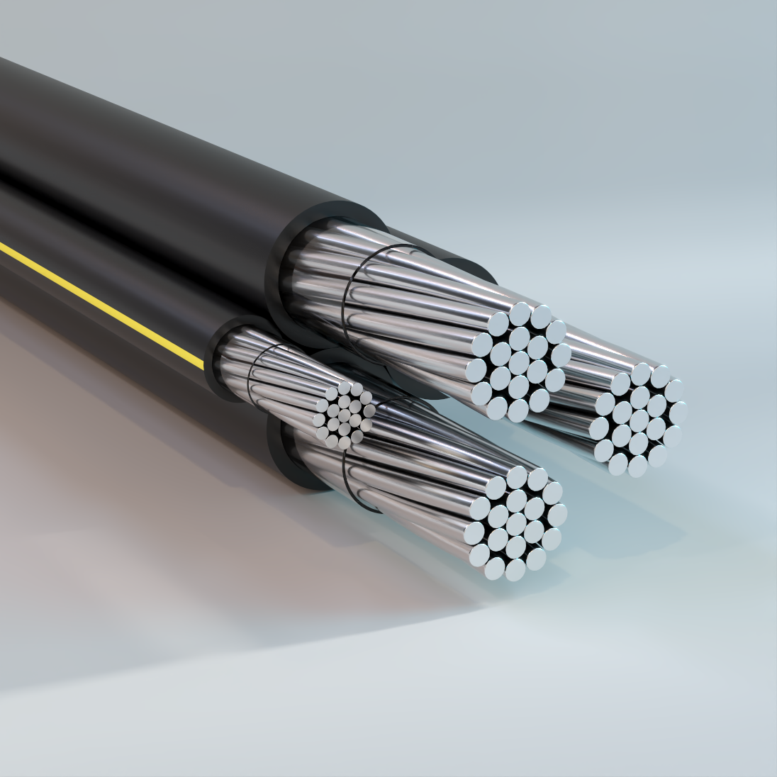
Secondary URD
Underground, Single/Duplex/Triplex/Quadruplex,, XLPE Insulated, 600V – Aluminum
Used for secondary distribution and underground service at 600 volts or less. May be used in ducts or direct burial.
Physical Data
| Single | ||||||
|---|---|---|---|---|---|---|
| Code Word |
Phase Conductor | XLPE Insulation | ||||
| Size AWG or kcmil |
Number of Strands |
Insulation Thickness mil |
Cable OD mil |
Code Word Suffix |
Net Weight lb/kft |
|
| Princeton | 6 | 7 | 60 | 0.31 | /XLP | 45 |
| Mercer | 4 | 7 | 60 | 0.35 | /XLP | 65 |
| Clemson | 2 | 7 | 60 | 0.41 | /XLP | 94 |
| Kenyon | 1 | 19 | 80 | 0.49 | /XLP | 125 |
| Harvard | 1/0 | 19 | 80 | 0.53 | /XLP | 150 |
| Yale | 2/0 | 19 | 80 | 0.57 | /XLP | 182 |
| Tufts | 3/0 | 19 | 80 | 0.62 | /XLP | 221 |
| Beloit | 4/0 | 19 | 80 | 0.68 | /XLP | 271 |
| Hofstra | 250 | 37 | 95 | 0.76 | /XLP | 323 |
| Gonzaga | 300 | 37 | 95 | 0.81 | /XLP | 377 |
| Rutgers | 350 | 37 | 95 | 0.86 | /XLP | 431 |
| Dartmouth | 400 | 37 | 95 | 0.91 | /XLP | 485 |
| Brown | 450 | 37 | 95 | 0.95 | /XLP | 539 |
| Emory | 500 | 37 | 95 | 0.99 | /XLP | 592 |
| Duke | 600 | 61 | 110 | 1.10 | /XLP | 711 |
| Furman | 700 | 61 | 110 | 1.17 | /XLP | 816 |
| Sewanee | 750 | 61 | 110 | 1.20 | /XLP | 870 |
| Fordham | 1000 | 61 | 110 | 1.35 | /XLP | 1129 |
| The above data are approximate and subject to normal manufacturing tolerances. Other sizes available upon request. | ||||||
| Duplex | ||||||||||
|---|---|---|---|---|---|---|---|---|---|---|
| Code Word |
Phase Conductor | Neutral Conductor | Cable OD | XLPE Insulation | ||||||
| Size AWG or kcmil |
Number of Strands |
Insulation Thickness mils |
Size AWG or kcmil |
Number of Strands |
Insulation Thickness mil |
Single Phase in |
Complete Cable in |
Code Word Suffix |
Net Weight | |
| lb/kft | ||||||||||
| Alcorn | 8 | 1 | 60 | 8 | 1 | 60 | 0.25 | 0.50 | /XLP/EYS | 62.2 |
| Claflin | 6 | 7 | 60 | 6 | 7 | 60 | 0.31 | 0.61 | /XLP/EYS | 92.8 |
| Delgado | 4 | 7 | 60 | 4 | 7 | 60 | 0.35 | 0.70 | /XLP/EYS | 131.7 |
| Cedarcrest | 2 | 7 | 60 | 4 | 7 | 60 | 0.41 | 0.82 | /XLP/EYS | 161.4 |
| Everett | 2 | 7 | 60 | 2 | 7 | 60 | 0.41 | 0.82 | /XLP/EYS | 191.2 |
| Findlay | 2/0 | 19 | 80 | 2/0 | 19 | 80 | 0.57 | 1.15 | /XLP/EYS | 372.0 |
| Hanover | 4/0 | 19 | 80 | 4/0 | 19 | 80 | 0.68 | 1.36 | /XLP/EYS | 552.1 |
| Glenville | 350 | 37 | 95 | 350 | 37 | 95 | 0.86 | 1.72 | /XLP/EYS | 880.2 |
| The above data are approximate and subject to normal manufacturing tolerances. Other sizes available upon request. | ||||||||||
| Triplex | ||||||||||
|---|---|---|---|---|---|---|---|---|---|---|
| Code Word |
Phase Conductor | Neutral Conductor | Cable OD | XLPE Insulation | ||||||
| Size AWG or kcmil |
Number of Strands |
Insulation Thickness mils |
Size AWG or kcmil |
Number of Strands |
Insulation Thickness mil |
Single Phase in |
Complete Cable in |
Code Word Suffix |
Net Weight | |
| lb/kft | ||||||||||
| Erskine | 6 | 7 | 60 | 6 | 7 | 60 | 0.31 | 0.66 | /XLP/EYS | 139 |
| Vassar | 4 | 7 | 60 | 4 | 7 | 60 | 0.35 | 0.76 | /XLP/EYS | 198 |
| Stephens | 2 | 7 | 60 | 4 | 7 | 60 | 0.41 | 0.88 | /XLP/EYS | 257 |
| Ramapo | 2 | 7 | 60 | 2 | 7 | 60 | 0.41 | 0.88 | /XLP/EYS | 287 |
| Grossmont | 1 | 19 | 80 | 1 | 19 | 80 | 0.49 | 1.06 | /XLP/EYS | 383 |
| Brenau | 1/0 | 19 | 80 | 2 | 7 | 60 | 0.53 | 1.14 | /XLP/EYS | 402 |
| Bergen | 1/0 | 19 | 80 | 1/0 | 19 | 80 | 0.53 | 1.14 | /XLP/EYS | 460 |
| Fisk | 2/0 | 19 | 80 | 2 | 7 | 60 | 0.57 | 1.24 | /XLP/EYS | 468 |
| Converse | 2/0 | 19 | 80 | 1 | 19 | 80 | 0.57 | 1.24 | /XLP/EYS | 500 |
| Shaw | 2/0 | 19 | 80 | 1/0 | 19 | 80 | 0.57 | 1.24 | /XLP/EYS | 525 |
| Hunter | 2/0 | 19 | 80 | 2/0 | 19 | 80 | 0.57 | 1.24 | /XLP/EYS | 558 |
| Calvert | 3/0 | 19 | 80 | 2 | 7 | 60 | 0.62 | 1.34 | /XLP/EYS | 547 |
| Chase | 3/0 | 19 | 80 | 1 | 19 | 80 | 0.62 | 1.34 | /XLP/EYS | 579 |
| Hollins | 3/0 | 19 | 80 | 1/0 | 19 | 80 | 0.62 | 1.34 | /XLP/EYS | 605 |
| Rockland | 3/0 | 19 | 80 | 3/0 | 19 | 80 | 0.62 | 1.34 | /XLP/EYS | 677 |
| Coburn | 4/0 | 19 | 80 | 1 | 19 | 80 | 0.68 | 1.47 | /XLP/EYS | 680 |
| Molloy | 4/0 | 19 | 80 | 1/0 | 19 | 80 | 0.68 | 1.47 | /XLP/EYS | 705 |
| Sweetbriar | 4/0 | 19 | 80 | 2/0 | 19 | 80 | 0.68 | 1.47 | /XLP/EYS | 738 |
| Monmouth | 4/0 | 19 | 80 | 4/0 | 19 | 80 | 0.68 | 1.47 | /XLP/EYS | 828 |
| Aquinas | 250 | 37 | 95 | 2/0 | 19 | 80 | 0.76 | 1.63 | /XLP/EYS | 844 |
| Pratt | 250 | 37 | 95 | 3/0 | 19 | 80 | 0.76 | 1.63 | /XLP/EYS | 884 |
| Yeshiva | 250 | 37 | 95 | 250 | 37 | 95 | 0.76 | 1.63 | /XLP/EYS | 987 |
| Allen | 300 | 37 | 95 | 2/0 | 19 | 80 | 0.81 | 1.75 | /XLP/EYS | 956 |
| Greenville | 350 | 37 | 95 | 1/0 | 19 | 80 | 0.86 | 1.85 | /XLP/EYS | 1034 |
| Gloucester | 350 | 37 | 95 | 3/0 | 19 | 80 | 0.86 | 1.85 | /XLP/EYS | 1106 |
| Wesleyan | 350 | 37 | 95 | 4/0 | 19 | 80 | 0.86 | 1.85 | /XLP/EYS | 1156 |
| Newark | 350 | 37 | 95 | 350 | 37 | 95 | 0.86 | 1.85 | /XLP/EYS | 1320 |
| Old Dominion | 500 | 37 | 95 | 4/0 | 19 | 80 | 0.99 | 2.13 | /XLP/EYS | 1483 |
| Holyoke | 500 | 37 | 95 | 300 | 37 | 95 | 0.99 | 2.13 | /XLP/EYS | 1592 |
| Rider | 500 | 37 | 95 | 350 | 37 | 95 | 0.99 | 2.13 | /XLP/EYS | 1647 |
| Westchester | 500 | 37 | 95 | 500 | 37 | 95 | 0.99 | 2.13 | /XLP/EYS | 1811 |
| Villanova | 750 | 61 | 110 | 350 | 37 | 95 | 1.20 | 2.58 | /XLP/EYS | 2215 |
| Voorhees | 750 | 61 | 110 | 450 | 37 | 95 | 1.20 | 2.58 | /XLP/EYS | 2324 |
| Fairfield | 750 | 61 | 110 | 500 | 37 | 95 | 1.20 | 2.58 | /XLP/EYS | 2379 |
| Seton Hall | 750 | 61 | 110 | 750 | 61 | 110 | 1.20 | 2.58 | /XLP/EYS | 2662 |
| The above data are approximate and subject to normal manufacturing tolerances. Other sizes available upon request. | ||||||||||
| Quadruplex | ||||||||||
|---|---|---|---|---|---|---|---|---|---|---|
| Code Word |
Phase Conductor | Neutral Conductor | Cable OD | XLPE Insulation | ||||||
| Size AWG or kcmil |
Number of Strands |
Insulation Thickness mils |
Size AWG or kcmil |
Number of Strands |
Insulation Thickness mil |
Single Phase in |
Complete Cable in |
Code Word Suffix |
Net Weight lb/kft |
|
| Tulsa | 4 | 7 | 60 | 4 | 7 | 60 | 0.35 | 0.85 | /XLP/EYS | 263 |
| Miami | 2 | 7 | 60 | 6 | 7 | 60 | 0.41 | 0.99 | /XLP/EYS | 333 |
| Dyke | 2 | 7 | 60 | 4 | 7 | 60 | 0.41 | 0.99 | /XLP/EYS | 353 |
| Wittenberg | 2 | 7 | 60 | 2 | 7 | 60 | 0.41 | 0.99 | /XLP/EYS | 382 |
| Notre Dame | 1/0 | 19 | 80 | 2 | 7 | 60 | 0.53 | 1.28 | /XLP/EYS | 556 |
| Purdue | 1/0 | 19 | 80 | 1/0 | 19 | 80 | 0.53 | 1.28 | /XLP/EYS | 614 |
| Syracuse | 2/0 | 19 | 80 | 1 | 19 | 80 | 0.57 | 1.39 | /XLP/EYS | 686 |
| Lafayette | 2/0 | 19 | 80 | 2/0 | 19 | 80 | 0.57 | 1.39 | /XLP/EYS | 744 |
| Swarthmore | 3/0 | 19 | 80 | 1/0 | 19 | 80 | 0.62 | 1.51 | /XLP/EYS | 831 |
| Davidson | 3/0 | 19 | 80 | 3/0 | 19 | 80 | 0.62 | 1.51 | /XLP/EYS | 903 |
| Mc Pherson | 4/0 | 19 | 80 | 2 | 7 | 60 | 0.68 | 1.64 | /XLP/EYS | 924 |
| Doane | 4/0 | 19 | 80 | 1/0 | 19 | 80 | 0.68 | 1.64 | /XLP/EYS | 981 |
| Wake Forest | 4/0 | 19 | 80 | 2/0 | 19 | 80 | 0.68 | 1.64 | /XLP/EYS | 1014 |
| Earlham | 4/0 | 19 | 80 | 4/0 | 19 | 80 | 0.68 | 1.64 | /XLP/EYS | 1104 |
| Rust | 250 | 37 | 95 | 3/0 | 19 | 80 | 0.76 | 1.83 | /XLP/EYS | 1213 |
| Palomar | 250 | 37 | 95 | 250 | 37 | 95 | 0.76 | 1.83 | /XLP/EYS | 1316 |
| Slippery Rock | 350 | 37 | 95 | 4/0 | 19 | 80 | 0.86 | 2.08 | /XLP/EYS | 1596 |
| Niagara | 350 | 37 | 95 | 350 | 37 | 95 | 0.86 | 2.08 | /XLP/EYS | 1760 |
| Morehouse | 500 | 37 | 95 | 300 | 37 | 95 | 0.99 | 2.39 | /XLP/EYS | 2196 |
| Wofford | 500 | 37 | 95 | 350 | 37 | 95 | 0.99 | 2.39 | /XLP/EYS | 2251 |
| Marshall | 500 | 37 | 95 | 500 | 37 | 95 | 0.99 | 2.39 | /XLP/EYS | 2415 |
| Westminster | 750 | 61 | 110 | 350 | 37 | 95 | 1.2 | 2.89 | /XLP/EYS | 3102 |
| Windham | 750 | 61 | 110 | 500 | 37 | 95 | 1.2 | 2.89 | /XLP/EYS | 3266 |
| Tabor | 750 | 61 | 110 | 750 | 61 | 110 | 1.2 | 2.89 | /XLP/EYS | 3550 |
| The above data are approximate and subject to normal manufacturing tolerances. Other sizes available upon request. | ||||||||||
Ampacity Data
| Cable Construction Single Insulated Conductor | ||
|---|---|---|
| Conductor Size AWG/kcmil |
Ampacity | |
| In Ducts | Direct Burial | |
| 6 | 65 | 90 |
| 4 | 85 | 120 |
| 2 | 115 | 155 |
| 1 | 130 | 175 |
| 1/0 | 150 | 200 |
| 2/0 | 170 | 225 |
| 3/0 | 195 | 250 |
| 4/0 | 225 | 290 |
| 250 | 250 | 320 |
| 300 | 280 | 355 |
| 350 | 305 | 385 |
| 500 | 370 | 465 |
| 600 | 410 | 510 |
| 700 | 440 | 550 |
| 750 | 470 | 580 |
| 1000 | 545 | 670 |
| * Conductor temperature of 90 °C; ambient temperature of 20 °C; RHO 90; 100% load factor for three conductor triplex, 3 phase operation. | ||
| Cable Construction 2PLX and 3PLX | ||
|---|---|---|
| Conductor Size AWG/kcmil |
Ampacity | |
| In Ducts | Direct Burial | |
| 8 | 55 | 70 |
| 6 | 70 | 95 |
| 4 | 90 | 125 |
| 2 | 120 | 165 |
| 1/0 | 160 | 215 |
| 2/0 | 180 | 245 |
| 3/0 | 205 | 280 |
| 4/0 | 240 | 315 |
| 350 | 320 | 415 |
| 500 | 395 | 495 |
| * Conductor temperature of 90 °C; ambient temperature of 20 °C; RHO 90; 100% load factor with neutral carrying only unbalanced load for triplex assemblies. | ||
| Cable Construction 4PLX | ||
|---|---|---|
| Conductor Size AWG/kcmil |
Ampacity | |
| In Ducts | Direct Burial | |
| 4 | 85 | 120 |
| 2 | 115 | 155 |
| 1/0 | 150 | 200 |
| 2/0 | 170 | 225 |
| 3/0 | 195 | 250 |
| 4/0 | 225 | 290 |
| 350 | 305 | 385 |
| 500 | 370 | 465 |
| * Conductor temperature of 90 °C; ambient temperature of 20 °C; RHO 90; 100% load factor with neutral carrying only unbalanced load. | ||
| Cable Construction Single Insulated Conductor | ||
|---|---|---|
| Conductor Size AWG/kcmil |
Ampacity | |
| 75 °C (167 °F) | 90 °C (194 °F) | |
| 12 | 30 | 35 |
| 10 | 40 | 45 |
| 8 | 55 | 60 |
| 6 | 75 | 85 |
| 4 | 100 | 115 |
| 3 | 115 | 130 |
| 2 | 135 | 150 |
| 1 | 155 | 175 |
| 1/0 | 180 | 205 |
| 2/0 | 210 | 235 |
| 3/0 | 240 | 270 |
| 4/0 | 280 | 315 |
| 250 | 315 | 355 |
| 300 | 350 | 395 |
| 350 | 395 | 445 |
| 400 | 425 | 480 |
| 500 | 485 | 545 |
| 600 | 545 | 615 |
| 700 | 595 | 670 |
| 750 | 620 | 700 |
| 800 | 645 | 725 |
| 900 | 700 | 790 |
| 1000 | 750 | 845 |
| 1250 | 855 | 965 |
| 1500 | 950 | 1070 |
| 1750 | 1050 | 1185 |
| 2000 | 1150 | 1295 |
| NEC Table 310.15(B)(17) (formerly Table 310.17) Allowable Ampacities of Single Insulated Conductors Rated Up to and Including 2000 V in Free Air, Based on Ambient Temperature of 30 °C (86 °F). | ||
| Cable Construction Single, 2PLX, 3PLX and 4PLX | ||
|---|---|---|
| Conductor Size AWG/kcmil |
Ampacity | |
| 75 °C (167 °F) | 90 °C (194 °F) | |
| 12 | 20 | 25 |
| 10 | 30 | 35 |
| 8 | 40 | 45 |
| 6 | 50 | 55 |
| 4 | 65 | 75 |
| 3 | 75 | 85 |
| 2 | 90 | 100 |
| 1 | 100 | 115 |
| 1/0 | 120 | 135 |
| 2/0 | 135 | 150 |
| 3/0 | 155 | 175 |
| 4/0 | 180 | 205 |
| 250 | 205 | 230 |
| 300 | 230 | 260 |
| 350 | 250 | 280 |
| 400 | 270 | 305 |
| 500 | 310 | 350 |
| 600 | 340 | 385 |
| 700 | 375 | 425 |
| 750 | 385 | 435 |
| 800 | 395 | 445 |
| 900 | 425 | 480 |
| 1000 | 445 | 500 |
| 1250 | 485 | 545 |
| 1500 | 520 | 585 |
| 1750 | 545 | 615 |
| 2000 | 560 | 630 |
| NEC Table 310.15(B)(16) (formerly Table 310.16) Allowable Ampacities of Insulated Conductors Rated Up to and Including 2000 V, 60 °C Through 90 °C (140 °F Through 194 °F), Not More Than Three Current-Carrying Conductors in Raceway, Cable, or Earth (Directly Buried), Based on Ambient Temperature of 30 °C (86 °F). | ||
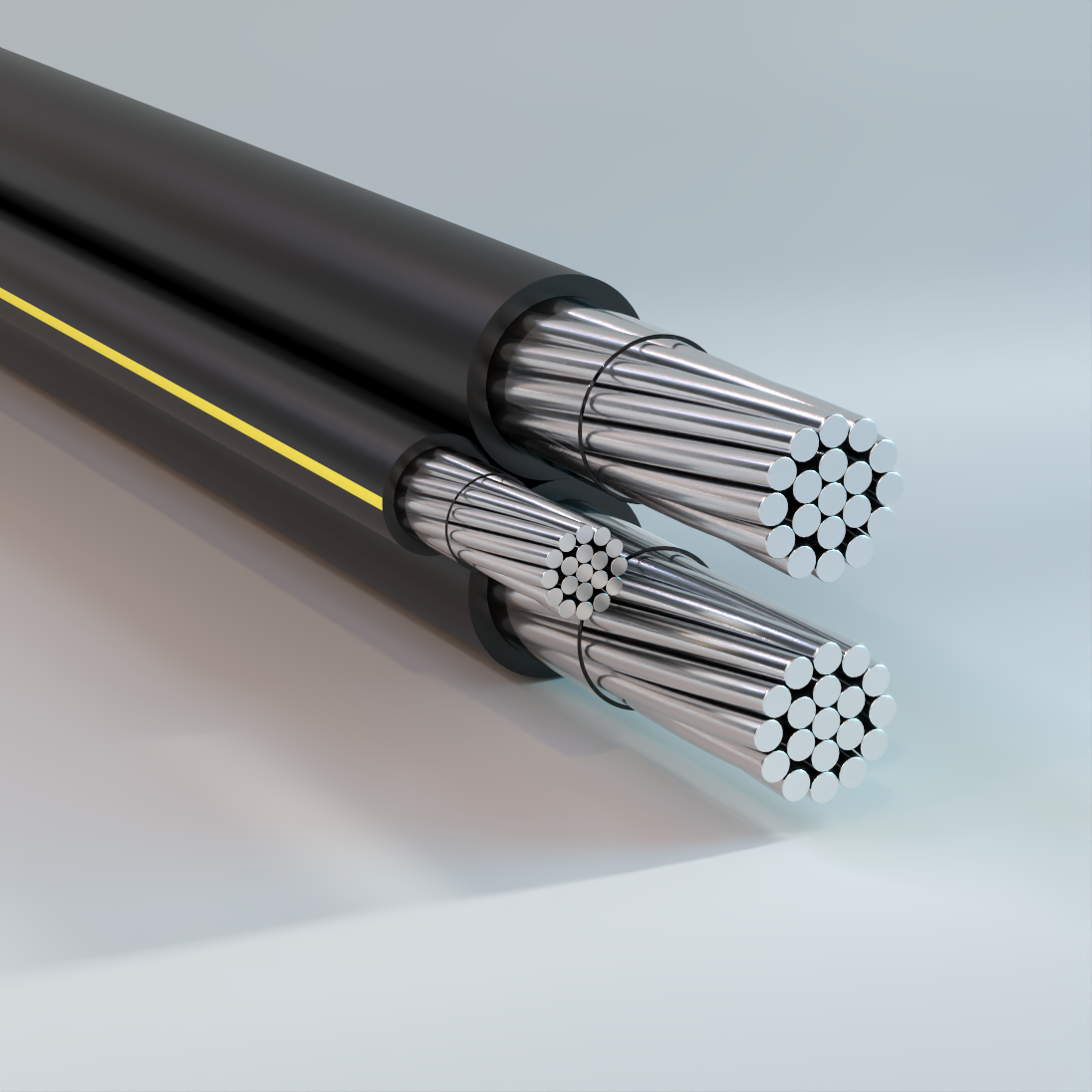
Secondary URD AA-8000, Tri-Rated
Underground, Triplex/Quadruplex, Compressed Conductor, XLPE Insulation, 600V – Aluminum
Used for secondary distribution and underground service at 600 volts or less. AA-8000 series aluminum alloy conductor is used for increased flexibility. May be used for secondary distribution and underground service at 600 volts or less. May be used in ducts or direct burial.
Physical Data
| Triplex AA-8000 Series Tri-Rated; USE-2/RHH/RHW-2; Compressed Conductor | ||||||||||
|---|---|---|---|---|---|---|---|---|---|---|
| Code Word |
Phase Conductor | Neutral Conductor | Cable OD | XLPE Insulation | ||||||
| Size AWG or kcmil |
Number of Strands |
Insulation Thickness mil |
Size AWG or kcmil |
Number of Strands |
Insulation Thickness mil |
Single Phase in |
Complete Cable in |
Code Word Suffix |
Net Weight lb/kft |
|
| Erskine | 6 | 7 | 60 | 6 | 7 | 60 | 0.31 | 0.66 | /XLP/EYS | 139 |
| Vassar | 4 | 7 | 60 | 4 | 7 | 60 | 0.35 | 0.76 | /XLP/EYS | 198 |
| Stephens | 2 | 7 | 60 | 4 | 7 | 60 | 0.41 | 0.88 | /XLP/EYS | 257 |
| Ramapo | 2 | 7 | 60 | 2 | 7 | 60 | 0.41 | 0.88 | /XLP/EYS | 287 |
| Grossmont | 1 | 19 | 80 | 1 | 19 | 80 | 0.49 | 1.06 | /XLP/EYS | 383 |
| Brenau | 1/0 | 19 | 80 | 2 | 7 | 60 | 0.53 | 1.14 | /XLP/EYS | 402 |
| Bergen | 1/0 | 19 | 80 | 1/0 | 19 | 80 | 0.53 | 1.14 | /XLP/EYS | 460 |
| Fisk | 2/0 | 19 | 80 | 2 | 7 | 60 | 0.57 | 1.24 | /XLP/EYS | 468 |
| Converse | 2/0 | 19 | 80 | 1 | 19 | 80 | 0.57 | 1.24 | /XLP/EYS | 500 |
| Shaw | 2/0 | 19 | 80 | 1/0 | 19 | 80 | 0.57 | 1.24 | /XLP/EYS | 525 |
| Hunter | 2/0 | 19 | 80 | 2/0 | 19 | 80 | 0.57 | 1.24 | /XLP/EYS | 558 |
| Calvert | 3/0 | 19 | 80 | 2 | 7 | 60 | 0.62 | 1.34 | /XLP/EYS | 547 |
| Chase | 3/0 | 19 | 80 | 1 | 19 | 80 | 0.62 | 1.34 | /XLP/EYS | 579 |
| Hollins | 3/0 | 19 | 80 | 1/0 | 19 | 80 | 0.62 | 1.34 | /XLP/EYS | 605 |
| Rockland | 3/0 | 19 | 80 | 3/0 | 19 | 80 | 0.62 | 1.34 | /XLP/EYS | 677 |
| Coburn | 4/0 | 19 | 80 | 1 | 19 | 80 | 0.68 | 1.47 | /XLP/EYS | 680 |
| Molloy | 4/0 | 19 | 80 | 1/0 | 19 | 80 | 0.68 | 1.47 | /XLP/EYS | 705 |
| Sweetbriar | 4/0 | 19 | 80 | 2/0 | 19 | 80 | 0.68 | 1.47 | /XLP/EYS | 738 |
| Monmouth | 4/0 | 19 | 80 | 4/0 | 19 | 80 | 0.68 | 1.47 | /XLP/EYS | 828 |
| Aquinas | 250 | 37 | 95 | 2/0 | 19 | 80 | 0.76 | 1.63 | /XLP/EYS | 844 |
| Pratt | 250 | 37 | 95 | 3/0 | 19 | 80 | 0.76 | 1.63 | /XLP/EYS | 884 |
| Yeshiva | 250 | 37 | 95 | 250 | 37 | 95 | 0.76 | 1.63 | /XLP/EYS | 987 |
| Allen | 300 | 37 | 95 | 2/0 | 19 | 80 | 0.81 | 1.75 | /XLP/EYS | 956 |
| Greenville | 350 | 37 | 95 | 1/0 | 19 | 80 | 0.86 | 1.85 | /XLP/EYS | 1034 |
| Gloucester | 350 | 37 | 95 | 3/0 | 19 | 80 | 0.86 | 1.85 | /XLP/EYS | 1106 |
| Wesleyan | 350 | 37 | 95 | 4/0 | 19 | 80 | 0.86 | 1.85 | /XLP/EYS | 1156 |
| Newark | 350 | 37 | 95 | 350 | 37 | 95 | 0.86 | 1.85 | /XLP/EYS | 1320 |
| Old Dominion | 500 | 37 | 95 | 4/0 | 19 | 80 | 0.99 | 2.13 | /XLP/EYS | 1483 |
| Holyoke | 500 | 37 | 95 | 300 | 37 | 95 | 0.99 | 2.13 | /XLP/EYS | 1592 |
| Rider | 500 | 37 | 95 | 350 | 37 | 95 | 0.99 | 2.13 | /XLP/EYS | 1647 |
| Westchester | 500 | 37 | 95 | 500 | 37 | 95 | 0.99 | 2.13 | /XLP/EYS | 1811 |
| Villanova | 750 | 61 | 110 | 350 | 37 | 95 | 1.2 | 2.58 | /XLP/EYS | 2215 |
| Voorhees | 750 | 61 | 110 | 450 | 37 | 95 | 1.2 | 2.58 | /XLP/EYS | 2324 |
| Fairfield | 750 | 61 | 110 | 500 | 37 | 95 | 1.2 | 2.58 | /XLP/EYS | 2379 |
| Seton Hall | 750 | 61 | 110 | 750 | 61 | 110 | 1.2 | 2.58 | /XLP/EYS | 2662 |
| The above data are approximate and subject to normal manufacturing tolerances. Other sizes available upon request. | ||||||||||
| Quadruplex AA-8000 Series Tri-Rated; USE-2/RHH/RHW-2; Compressed Conductor | ||||||||||
|---|---|---|---|---|---|---|---|---|---|---|
| Code Word |
Phase Conductor | Neutral Conductor | Cable OD | XLPE Insulation | ||||||
| Size AWG or kcmil |
Number of Strands |
Insulation Thickness |
Size AWG or kcmil |
Number of Strands |
Insulation Thickness |
Single Phase |
Complete Cable | Code Word Suffix |
Net Weight | |
| mil | mil | in | in | lb/kft | ||||||
| Tulsa | 4 | 7 | 60 | 4 | 7 | 60 | 0.35 | 0.85 | /XLP/EYS | 263 |
| Miami | 2 | 7 | 60 | 6 | 7 | 60 | 0.41 | 0.99 | /XLP/EYS | 333 |
| Dyke | 2 | 7 | 60 | 4 | 7 | 60 | 0.41 | 0.99 | /XLP/EYS | 353 |
| Wittenberg | 2 | 7 | 60 | 2 | 7 | 60 | 0.41 | 0.99 | /XLP/EYS | 382 |
| Notre Dame | 1/0 | 19 | 80 | 2 | 7 | 60 | 0.53 | 1.28 | /XLP/EYS | 556 |
| Purdue | 1/0 | 19 | 80 | 1/0 | 19 | 80 | 0.53 | 1.28 | /XLP/EYS | 614 |
| Syracuse | 2/0 | 19 | 80 | 1 | 19 | 80 | 0.57 | 1.39 | /XLP/EYS | 686 |
| Lafayette | 2/0 | 19 | 80 | 2/0 | 19 | 80 | 0.57 | 1.39 | /XLP/EYS | 744 |
| Swarthmore | 3/0 | 19 | 80 | 1/0 | 19 | 80 | 0.62 | 1.51 | /XLP/EYS | 831 |
| Davidson | 3/0 | 19 | 80 | 3/0 | 19 | 80 | 0.62 | 1.51 | /XLP/EYS | 903 |
| Mc Pherson | 4/0 | 19 | 80 | 2 | 7 | 60 | 0.68 | 1.64 | /XLP/EYS | 924 |
| Doane | 4/0 | 19 | 80 | 1/0 | 19 | 80 | 0.68 | 1.64 | /XLP/EYS | 981 |
| Wake Forest | 4/0 | 19 | 80 | 2/0 | 19 | 80 | 0.68 | 1.64 | /XLP/EYS | 1014 |
| Earlham | 4/0 | 19 | 80 | 4/0 | 19 | 80 | 0.68 | 1.64 | /XLP/EYS | 1104 |
| Rust | 250 | 37 | 95 | 3/0 | 19 | 80 | 0.76 | 1.83 | /XLP/EYS | 1213 |
| Palomar | 250 | 37 | 95 | 250 | 37 | 95 | 0.76 | 1.83 | /XLP/EYS | 1316 |
| Slippery Rock | 350 | 37 | 95 | 4/0 | 19 | 80 | 0.86 | 2.08 | /XLP/EYS | 1596 |
| Pomona | 350 | 37 | 95 | 350 | 37 | 95 | 0.86 | 2.08 | /XLP/EYS | 1760 |
| Morehouse | 500 | 37 | 95 | 300 | 37 | 95 | 0.99 | 2.39 | /XLP/EYS | 2196 |
| Wofford | 500 | 37 | 95 | 350 | 37 | 95 | 0.99 | 2.39 | /XLP/EYS | 2251 |
| Marshall | 500 | 37 | 95 | 500 | 37 | 95 | 0.99 | 2.39 | /XLP/EYS | 2415 |
| Westminster | 750 | 61 | 110 | 350 | 37 | 95 | 1.2 | 2.89 | /XLP/EYS | 3102 |
| Windham | 750 | 61 | 110 | 500 | 37 | 95 | 1.2 | 2.89 | /XLP/EYS | 3266 |
| The above data are approximate and subject to normal manufacturing tolerances. Other sizes available upon request. | ||||||||||
Ampacity Data
| Cable Construction Single Insulated Conductor | ||
|---|---|---|
| Conductor Size AWG/kcmil |
Ampacity | |
| In Ducts | Direct Burial | |
| 6 | 65 | 90 |
| 4 | 85 | 120 |
| 2 | 115 | 155 |
| 1 | 130 | 175 |
| 1/0 | 150 | 200 |
| 2/0 | 170 | 225 |
| 3/0 | 195 | 250 |
| 4/0 | 225 | 290 |
| 250 | 250 | 320 |
| 300 | 280 | 355 |
| 350 | 305 | 385 |
| 500 | 370 | 465 |
| 600 | 410 | 510 |
| 700 | 440 | 550 |
| 750 | 470 | 580 |
| 1000 | 545 | 670 |
| * Conductor temperature of 90 °C; ambient temperature of 20 °C; RHO 90; 100% load factor for three conductor triplex, 3 phase operation. | ||
| Cable Construction 2PLX and 3PLX | ||
|---|---|---|
| Conductor Size AWG/kcmil |
Ampacity | |
| In Ducts | Direct Burial | |
| 8 | 55 | 70 |
| 6 | 70 | 95 |
| 4 | 90 | 125 |
| 2 | 120 | 165 |
| 1/0 | 160 | 215 |
| 2/0 | 180 | 245 |
| 3/0 | 205 | 280 |
| 4/0 | 240 | 315 |
| 350 | 320 | 415 |
| 500 | 395 | 495 |
| * Conductor temperature of 90 °C; ambient temperature of 20 °C; RHO 90; 100% load factor with neutral carrying only unbalanced load for triplex assemblies. | ||
| Cable Construction 4PLX | ||
|---|---|---|
| Conductor Size AWG/kcmil |
Ampacity | |
| In Ducts | Direct Burial | |
| 4 | 85 | 120 |
| 2 | 115 | 155 |
| 1/0 | 150 | 200 |
| 2/0 | 170 | 225 |
| 3/0 | 195 | 250 |
| 4/0 | 225 | 290 |
| 350 | 305 | 385 |
| 500 | 370 | 465 |
| * Conductor temperature of 90 °C; ambient temperature of 20 °C; RHO 90; 100% load factor with neutral carrying only unbalanced load. | ||
| Cable Construction Single Insulated Conductor | ||
|---|---|---|
| Conductor Size AWG/kcmil |
Ampacity | |
| 75 °C (167 °F) | 90 °C (194 °F) | |
| 12 | 30 | 35 |
| 10 | 40 | 45 |
| 8 | 55 | 60 |
| 6 | 75 | 85 |
| 4 | 100 | 115 |
| 3 | 115 | 130 |
| 2 | 135 | 150 |
| 1 | 155 | 175 |
| 1/0 | 180 | 205 |
| 2/0 | 210 | 235 |
| 3/0 | 240 | 270 |
| 4/0 | 280 | 315 |
| 250 | 315 | 355 |
| 300 | 350 | 395 |
| 350 | 395 | 445 |
| 400 | 425 | 480 |
| 500 | 485 | 545 |
| 600 | 545 | 615 |
| 700 | 595 | 670 |
| 750 | 620 | 700 |
| 800 | 645 | 725 |
| 900 | 700 | 790 |
| 1000 | 750 | 845 |
| 1250 | 855 | 965 |
| 1500 | 950 | 1070 |
| 1750 | 1050 | 1185 |
| 2000 | 1150 | 1295 |
| NEC Table 310.15(B)(17) (formerly Table 310.17) Allowable Ampacities of Single Insulated Conductors Rated Up to and Including 2000 V in Free Air, Based on Ambient Temperature of 30 °C (86 °F). | ||
| Cable Construction Single, 2PLX, 3PLX and 4PLX | ||
|---|---|---|
| Conductor Size AWG/kcmil |
Ampacity | |
| 75 °C (167 °F) | 90 °C (194 °F) | |
| 12 | 20 | 25 |
| 10 | 30 | 35 |
| 8 | 40 | 45 |
| 6 | 50 | 55 |
| 4 | 65 | 75 |
| 3 | 75 | 85 |
| 2 | 90 | 100 |
| 1 | 100 | 115 |
| 1/0 | 120 | 135 |
| 2/0 | 135 | 150 |
| 3/0 | 155 | 175 |
| 4/0 | 180 | 205 |
| 250 | 205 | 230 |
| 300 | 230 | 260 |
| 350 | 250 | 280 |
| 400 | 270 | 305 |
| 500 | 310 | 350 |
| 600 | 340 | 385 |
| 700 | 375 | 425 |
| 750 | 385 | 435 |
| 800 | 395 | 445 |
| 900 | 425 | 480 |
| 1000 | 445 | 500 |
| 1250 | 485 | 545 |
| 1500 | 520 | 585 |
| 1750 | 545 | 615 |
| 2000 | 560 | 630 |
| NEC Table 310.15(B)(16) (formerly Table 310.16) Allowable Ampacities of Insulated Conductors Rated Up to and Including 2000 V, 60 °C Through 90 °C (140 °F Through 194 °F), Not More Than Three Current-Carrying Conductors in Raceway, Cable, or Earth (Directly Buried), Based on Ambient Temperature of 30 °C (86 °F). | ||
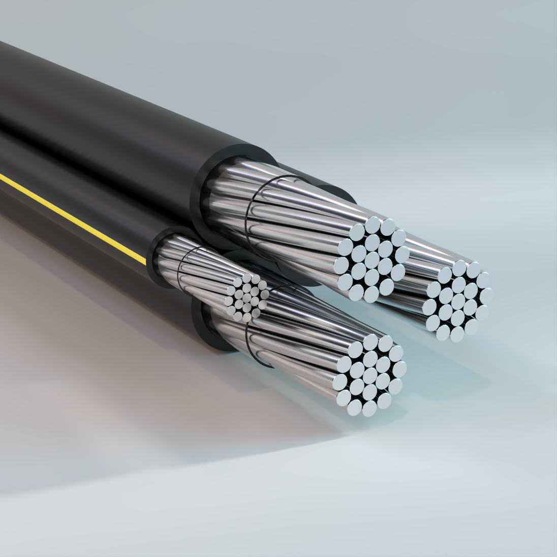
Secondary URD Ruggedized
Underground, Single/Duplex/Triplex/Quadruplex, XLPE Insulation, 600V – Aluminum
Used for secondary distribution and underground service at 600 volts or less. May be used in ducts or direct burial. It’s tougher and more durable construction gives it superior mechanical performance for direct burial use.
Physical Data
| Single | ||||||
|---|---|---|---|---|---|---|
| Code Word |
Phase Conductor | XLPE Insulation | ||||
| Size AWG or kcmil |
Number of Strands |
Insulation Thickness |
Cable OD |
Code Word Suffix |
Net Weight |
|
| mil | mil | lb/kft | ||||
| Princeton | 6 | 7 | 60 | 0.31 | /XLP/AR | 46 |
| Mercer | 4 | 7 | 60 | 0.35 | /XLP/AR | 65 |
| Clemson | 2 | 7 | 60 | 0.41 | /XLP/AR | 94 |
| Kenyon | 1 | 19 | 80 | 0.49 | /XLP/AR | 127 |
| Harvard | 1/0 | 19 | 80 | 0.53 | /XLP/AR | 153 |
| Yale | 2/0 | 19 | 80 | 0.57 | /XLP/AR | 186 |
| Tufts | 3/0 | 19 | 80 | 0.62 | /XLP/AR | 225 |
| Beloit | 4/0 | 19 | 80 | 0.68 | /XLP/AR | 276 |
| Hofstra | 250 | 37 | 95 | 0.76 | /XLP/AR | 334 |
| Gonzaga | 300 | 37 | 95 | 0.81 | /XLP/AR | 390 |
| Rutgers | 350 | 37 | 95 | 0.86 | /XLP/AR | 447 |
| Dartmouth | 400 | 37 | 95 | 0.91 | /XLP/AR | 503 |
| Brown | 450 | 37 | 95 | 0.95 | /XLP/AR | 558 |
| Emory | 500 | 37 | 95 | 0.99 | /XLP/AR | 613 |
| Duke | 600 | 61 | 110 | 1.10 | /XLP/AR | 744 |
| Furman | 700 | 61 | 110 | 1.17 | /XLP/AR | 855 |
| Sewanee | 750 | 61 | 110 | 1.20 | /XLP/AR | 911 |
| Fordham | 1000 | 61 | 110 | 1.35 | /XLP/AR | 1183 |
| The above data are approximate and subject to normal manufacturing tolerances. Other sizes available upon request. | ||||||
| Duplex | ||||||||||
|---|---|---|---|---|---|---|---|---|---|---|
| Code Word |
Phase Conductor | Neutral Conductor | Cable OD | XLPE Insulation | ||||||
| Size AWG or kcmil |
Number of Strands |
Insulation Thickness |
Size AWG or kcmil |
Number of Strands |
Insulation Thickness |
Single Phase |
Complete Cable |
Code Word Suffix |
Net Weight |
|
| mil | mil | mil | in | lb/kft | ||||||
| Alcorn | 8 | 1 | 60 | 8 | 1 | 60 | 0.25 | 0.50 | /XLP/AR/EYS | 63 |
| Claflin | 6 | 7 | 60 | 6 | 7 | 60 | 0.31 | 0.61 | /XLP/AR/EYS | 93 |
| Delgado | 4 | 1 | 60 | 4 | 7 | 60 | 0.35 | 0.70 | /XLP/AR/EYS | 132 |
| Cedarcrest | 2 | 7 | 60 | 4 | 7 | 60 | 0.41 | 0.82 | /XLP/AR/EYS | 161 |
| Everett | 2 | 7 | 60 | 2 | 7 | 60 | 0.41 | 0.82 | /XLP/AR/EYS | 191 |
| Findlay | 2/0 | 7 | 80 | 2/0 | 19 | 80 | 0.57 | 1.15 | /XLP/AR/EYS | 374 |
| Hanover | 4/0 | 19 | 80 | 4/0 | 19 | 80 | 0.68 | 1.36 | /XLP/AR/EYS | 556 |
| Glenville | 350 | 37 | 95 | 350 | 37 | 95 | 0.86 | 1.72 | /XLP/AR/EYS | 893 |
| The above data are approximate and subject to normal manufacturing tolerances. Other sizes available upon request. Ampacities: Refer to Ampacity Data. |
||||||||||
| Triplex | ||||||||||
|---|---|---|---|---|---|---|---|---|---|---|
| Code Word |
Phase Conductor | Neutral Conductor | Cable OD | XLPE Insulation | ||||||
| Size AWG or kcmil |
Number of Strands |
Insulation Thickness |
Size AWG or kcmil |
Number of Strands |
Insulation Thickness |
Single Phase |
Complete Cable |
Code Word Suffix |
Net Weight |
|
| mil | mil | mil | in | lb/kft | ||||||
| Erskine | 6 | 7 | 60 | 6 | 7 | 60 | 0.31 | 0.66 | /XLP/AR/EYS | 140 |
| Vassar | 4 | 7 | 60 | 4 | 7 | 60 | 0.35 | 0.76 | /XLP/AR/EYS | 198 |
| Stephens | 2 | 7 | 60 | 4 | 7 | 60 | 0.41 | 0.88 | /XLP/AR/EYS | 258 |
| Ramapo | 2 | 7 | 60 | 2 | 7 | 60 | 0.41 | 0.88 | /XLP/AR/EYS | 288 |
| Grossmont | 1 | 19 | 80 | 1 | 19 | 80 | 0.49 | 1.06 | /XLP/AR/EYS | 390 |
| Brenau | 1/0 | 19 | 80 | 2 | 7 | 60 | 0.53 | 1.14 | /XLP/AR/EYS | 408 |
| Bergen | 1/0 | 19 | 80 | 1/0 | 19 | 80 | 0.53 | 1.14 | /XLP/AR/EYS | 468 |
| Fisk | 2/0 | 19 | 80 | 2 | 7 | 60 | 0.57 | 1.24 | /XLP/AR/EYS | 475 |
| Converse | 2/0 | 19 | 80 | 1 | 19 | 80 | 0.57 | 1.24 | /XLP/AR/EYS | 509 |
| Shaw | 2/0 | 19 | 80 | 1/0 | 19 | 80 | 0.57 | 1.24 | /XLP/AR/EYS | 535 |
| Hunter | 2/0 | 19 | 80 | 2/0 | 19 | 80 | 0.57 | 1.24 | /XLP/AR/EYS | 568 |
| Calvert | 3/0 | 19 | 80 | 2 | 7 | 60 | 0.62 | 1.34 | /XLP/AR/EYS | 556 |
| Chase | 3/0 | 19 | 80 | 1 | 19 | 80 | 0.62 | 1.34 | /XLP/AR/EYS | 590 |
| Hollins | 3/0 | 19 | 80 | 1/0 | 19 | 80 | 0.62 | 1.34 | /XLP/AR/EYS | 616 |
| Rockland | 3/0 | 19 | 80 | 3/0 | 19 | 80 | 0.62 | 1.34 | /XLP/AR/EYS | 690 |
| Coburn | 4/0 | 19 | 80 | 1 | 19 | 80 | 0.68 | 1.47 | /XLP/AR/EYS | 692 |
| Molloy | 4/0 | 19 | 80 | 1/0 | 19 | 80 | 0.68 | 1.47 | /XLP/AR/EYS | 719 |
| Sweetbriar | 4/0 | 19 | 80 | 2/0 | 19 | 80 | 0.68 | 1.47 | /XLP/AR/EYS | 752 |
| Monmouth | 4/0 | 19 | 80 | 4/0 | 19 | 80 | 0.68 | 1.47 | /XLP/AR/EYS | 844 |
| Aquinas | 250 | 37 | 95 | 2/0 | 19 | 80 | 0.76 | 1.63 | /XLP/AR/EYS | 870 |
| Pratt | 250 | 37 | 95 | 3/0 | 19 | 80 | 0.76 | 1.63 | /XLP/AR/EYS | 910 |
| Yeshiva | 250 | 37 | 95 | 250 | 37 | 95 | 0.76 | 1.63 | /XLP/AR/EYS | 1021 |
| Allen | 300 | 37 | 95 | 2/0 | 19 | 80 | 0.81 | 1.75 | /XLP/AR/EYS | 986 |
| Greenville | 350 | 37 | 95 | 1/0 | 19 | 80 | 0.86 | 1.85 | /XLP/AR/EYS | 1067 |
| Gloucester | 350 | 37 | 95 | 3/0 | 19 | 80 | 0.86 | 1.85 | /XLP/AR/EYS | 1141 |
| Wesleyan | 350 | 37 | 95 | 4/0 | 19 | 80 | 0.86 | 1.85 | /XLP/AR/EYS | 1192 |
| Newark | 350 | 37 | 95 | 350 | 37 | 95 | 0.86 | 1.85 | /XLP/AR/EYS | 1367 |
| Old Dominion | 500 | 37 | 95 | 4/0 | 19 | 80 | 0.99 | 2.13 | /XLP/AR/EYS | 1532 |
| Holyoke | 500 | 37 | 95 | 300 | 37 | 95 | 0.99 | 2.13 | /XLP/AR/EYS | 1649 |
| Rider | 500 | 37 | 95 | 350 | 37 | 95 | 0.99 | 2.13 | /XLP/AR/EYS | 1707 |
| Westchester | 500 | 37 | 95 | 500 | 37 | 95 | 0.99 | 2.13 | /XLP/AR/EYS | 1877 |
| Villanova | 750 | 61 | 110 | 350 | 37 | 95 | 1.2 | 2.58 | /XLP/AR/EYS | 2314 |
| Voorhees | 750 | 61 | 110 | 450 | 37 | 95 | 1.2 | 2.58 | /XLP/AR/EYS | 2428 |
| Fairfield | 750 | 61 | 110 | 500 | 37 | 95 | 1.2 | 2.58 | /XLP/AR/EYS | 2484 |
| Seton Hall | 750 | 61 | 110 | 750 | 61 | 110 | 1.2 | 2.58 | /XLP/AR/EYS | 2788 |
| The above data are approximate and subject to normal manufacturing tolerances. Other sizes available upon request. | ||||||||||
| Quadruplex | ||||||||||
|---|---|---|---|---|---|---|---|---|---|---|
| Code Word |
Phase Conductor | Neutral Conductor | Cable OD | XLPE Insulation | ||||||
| Size AWG or kcmil |
Number of Strands |
Insulation Thickness |
Size AWG or kcmil |
Number of Strands |
Insulation Thickness |
Single Phase |
Complete Cable |
Code Word Suffix |
Net Weight |
|
| mil | mil | mil | in | lb/kft | ||||||
| Tulsa | 4 | 7 | 60 | 4 | 7 | 60 | 0.35 | 0.85 | /XLP/AR/EYS | 264 |
| Miami | 2 | 7 | 60 | 6 | 7 | 60 | 0.41 | 0.99 | /XLP/AR/EYS | 334 |
| Dyke | 2 | 7 | 60 | 4 | 7 | 60 | 0.41 | 0.99 | /XLP/AR/EYS | 354 |
| Wittenberg | 2 | 7 | 60 | 2 | 7 | 60 | 0.41 | 0.99 | /XLP/AR/EYS | 383 |
| Notre Dame | 1/0 | 19 | 80 | 2 | 7 | 60 | 0.53 | 1.28 | /XLP/AR/EYS | 564 |
| Purdue | 1/0 | 19 | 80 | 1/0 | 19 | 80 | 0.53 | 1.28 | /XLP/AR/EYS | 622 |
| Syracuse | 2/0 | 19 | 80 | 1 | 19 | 80 | 0.57 | 1.39 | /XLP/AR/EYS | 696 |
| Lafayette | 2/0 | 19 | 80 | 2/0 | 19 | 80 | 0.57 | 1.39 | /XLP/AR/EYS | 754 |
| Swarthmore | 3/0 | 19 | 80 | 1/0 | 19 | 80 | 0.62 | 1.51 | /XLP/AR/EYS | 843 |
| Davidson | 3/0 | 19 | 80 | 3/0 | 19 | 80 | 0.62 | 1.51 | /XLP/AR/EYS | 915 |
| McPherson | 4/0 | 19 | 80 | 2 | 7 | 60 | 0.68 | 1.64 | /XLP/AR/EYS | 939 |
| Doane | 4/0 | 19 | 80 | 1/0 | 19 | 80 | 0.68 | 1.64 | /XLP/AR/EYS | 997 |
| Wake Forest | 4/0 | 19 | 80 | 2/0 | 19 | 80 | 0.68 | 1.64 | /XLP/AR/EYS | 1030 |
| Earlham | 4/0 | 19 | 80 | 4/0 | 19 | 80 | 0.68 | 1.64 | /XLP/AR/EYS | 1120 |
| Rust | 250 | 37 | 95 | 3/0 | 19 | 80 | 0.76 | 1.83 | /XLP/AR/EYS | 1246 |
| Palomar | 250 | 37 | 95 | 250 | 37 | 95 | 0.76 | 1.83 | /XLP/AR/EYS | 1350 |
| None | 336.4 | 37 | 95 | 336.4 | 37 | 95 | 0.87 | 2.09 | /XLP/AR/EYS | 1752 |
| Susquehanna | 350 | 37 | 95 | 4/0 | 19 | 80 | 0.86 | 2.08 | /XLP/AR/EYS | 1643 |
| Pomona | 350 | 37 | 95 | 350 | 37 | 95 | 0.86 | 2.08 | /XLP/AR/EYS | 1807 |
| Morehouse | 500 | 37 | 95 | 300 | 37 | 95 | 0.99 | 2.39 | /XLP/AR/EYS | 2261 |
| Wofford | 500 | 37 | 95 | 350 | 37 | 95 | 0.99 | 2.39 | /XLP/AR/EYS | 2317 |
| Marshall | 500 | 37 | 95 | 500 | 37 | 95 | 0.99 | 2.39 | /XLP/AR/EYS | 2480 |
| Westminster | 750 | 61 | 110 | 350 | 37 | 95 | 1.2 | 2.89 | /XLP/AR/EYS | 3228 |
| Windham | 750 | 61 | 110 | 500 | 37 | 95 | 1.2 | 2.89 | /XLP/AR/EYS | 3391 |
| Tabor | 750 | 61 | 110 | 750 | 61 | 110 | 1.2 | 2.89 | /XLP/AR/EYS | 3675 |
| The above data are approximate and subject to normal manufacturing tolerances. Other sizes available upon request. | ||||||||||
Ampacity Data
| Cable Construction Single Insulated Conductor | ||
|---|---|---|
| Conductor Size AWG/kcmil |
Ampacity | |
| In Ducts | Direct Burial | |
| 6 | 65 | 90 |
| 4 | 85 | 120 |
| 2 | 115 | 155 |
| 1 | 130 | 175 |
| 1/0 | 150 | 200 |
| 2/0 | 170 | 225 |
| 3/0 | 195 | 250 |
| 4/0 | 225 | 290 |
| 250 | 250 | 320 |
| 300 | 280 | 355 |
| 350 | 305 | 385 |
| 500 | 370 | 465 |
| 600 | 410 | 510 |
| 700 | 440 | 550 |
| 750 | 470 | 580 |
| 1000 | 545 | 670 |
| * Conductor temperature of 90 °C; ambient temperature of 20 °C; RHO 90; 100% load factor for three conductor triplex, 3 phase operation. | ||
| Cable Construction 2PLX and 3PLX | ||
|---|---|---|
| Conductor Size AWG/kcmil |
Ampacity | |
| In Ducts | Direct Burial | |
| 8 | 55 | 70 |
| 6 | 70 | 95 |
| 4 | 90 | 125 |
| 2 | 120 | 165 |
| 1/0 | 160 | 215 |
| 2/0 | 180 | 245 |
| 3/0 | 205 | 280 |
| 4/0 | 240 | 315 |
| 350 | 320 | 415 |
| 500 | 395 | 495 |
| * Conductor temperature of 90 °C; ambient temperature of 20 °C; RHO 90; 100% load factor with neutral carrying only unbalanced load for triplex assemblies. | ||
| Cable Construction 4PLX | ||
|---|---|---|
| Conductor Size AWG/kcmil |
Ampacity | |
| In Ducts | Direct Burial | |
| 4 | 85 | 120 |
| 2 | 115 | 155 |
| 1/0 | 150 | 200 |
| 2/0 | 170 | 225 |
| 3/0 | 195 | 250 |
| 4/0 | 225 | 290 |
| 350 | 305 | 385 |
| 500 | 370 | 465 |
| * Conductor temperature of 90 °C; ambient temperature of 20 °C; RHO 90; 100% load factor with neutral carrying only unbalanced load. | ||
| Cable Construction Single Insulated Conductor | ||
|---|---|---|
| Conductor Size AWG/kcmil |
Ampacity | |
| 75 °C (167 °F) | 90 °C (194 °F) | |
| 12 | 30 | 35 |
| 10 | 40 | 45 |
| 8 | 55 | 60 |
| 6 | 75 | 85 |
| 4 | 100 | 115 |
| 3 | 115 | 130 |
| 2 | 135 | 150 |
| 1 | 155 | 175 |
| 1/0 | 180 | 205 |
| 2/0 | 210 | 235 |
| 3/0 | 240 | 270 |
| 4/0 | 280 | 315 |
| 250 | 315 | 355 |
| 300 | 350 | 395 |
| 350 | 395 | 445 |
| 400 | 425 | 480 |
| 500 | 485 | 545 |
| 600 | 545 | 615 |
| 700 | 595 | 670 |
| 750 | 620 | 700 |
| 800 | 645 | 725 |
| 900 | 700 | 790 |
| 1000 | 750 | 845 |
| 1250 | 855 | 965 |
| 1500 | 950 | 1070 |
| 1750 | 1050 | 1185 |
| 2000 | 1150 | 1295 |
| NEC Table 310.15(B)(17) (formerly Table 310.17) Allowable Ampacities of Single Insulated Conductors Rated Up to and Including 2000 V in Free Air, Based on Ambient Temperature of 30 °C (86 °F). | ||
| Cable Construction Single, 2PLX, 3PLX and 4PLX | ||
|---|---|---|
| Conductor Size AWG/kcmil |
Ampacity | |
| 75 °C (167 °F) | 90 °C (194 °F) | |
| 12 | 20 | 25 |
| 10 | 30 | 35 |
| 8 | 40 | 45 |
| 6 | 50 | 55 |
| 4 | 65 | 75 |
| 3 | 75 | 85 |
| 2 | 90 | 100 |
| 1 | 100 | 115 |
| 1/0 | 120 | 135 |
| 2/0 | 135 | 150 |
| 3/0 | 155 | 175 |
| 4/0 | 180 | 205 |
| 250 | 205 | 230 |
| 300 | 230 | 260 |
| 350 | 250 | 280 |
| 400 | 270 | 305 |
| 500 | 310 | 350 |
| 600 | 340 | 385 |
| 700 | 375 | 425 |
| 750 | 385 | 435 |
| 800 | 395 | 445 |
| 900 | 425 | 480 |
| 1000 | 445 | 500 |
| 1250 | 485 | 545 |
| 1500 | 520 | 585 |
| 1750 | 545 | 615 |
| 2000 | 560 | 630 |
| NEC Table 310.15(B)(16) (formerly Table 310.16) Allowable Ampacities of Insulated Conductors Rated Up to and Including 2000 V, 60 °C Through 90 °C (140 °F Through 194 °F), Not More Than Three Current-Carrying Conductors in Raceway, Cable, or Earth (Directly Buried), Based on Ambient Temperature of 30 °C (86 °F). | ||
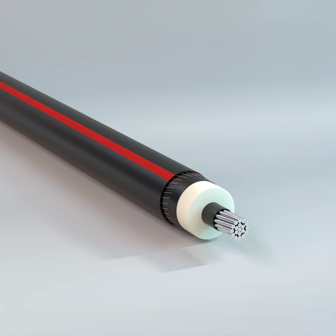
Primary UD
Underground, TR-XLPE Insulation, LLDPE Jacket, Concentric Neutral, 5kV-35kV – Aluminum
Used for underground primary residential and commercial distribution circuits. May be used in wet or dry locations, installed in underground ducts or direct burial.
Physical Data
| 5 kV TR-XLPE Insulated | ||||||||||||
|---|---|---|---|---|---|---|---|---|---|---|---|---|
| CME Spec Table | ||||||||||||
| Size AWG or kcmil |
Number of Strands |
Nominal OD Over Insulation |
1/3 Neutral | Full Neutral | ||||||||
| in | Number of Wires |
Size | Jacket Thickness |
Approximate Outside Diameter |
Approximate Net Weight |
Number of Wires |
Size | Jacket Thickness |
Approximate Outside Diameter |
Approximate Net Weight |
||
| AWG | mil | in | lb/kft | AWG | mil | in | lb/kft | |||||
| Copper 100% Insulation Level (90 mil) | ||||||||||||
| 2 | 7 | 0.50 | 6 | 14 | 50 | 0.81 | 469 | 16 | 14 | 50 | 0.81 | 589 |
| 1 | 19 | 0.54 | 7 | 14 | 50 | 0.84 | 547 | 13 | 12 | 50 | 0.88 | 730 |
| 1/0 | 19 | 0.58 | 9 | 14 | 50 | 0.88 | 653 | 16 | 12 | 50 | 0.92 | 870 |
| 2/0 | 19 | 0.63 | 11 | 14 | 50 | 0.93 | 779 | 13 | 10 | 50 | 1.00 | 1089 |
| 3/0 | 19 | 0.68 | 14 | 14 | 50 | 0.98 | 941 | 16 | 10 | 50 | 1.05 | 1309 |
| 4/0 | 19 | 0.73 | 18 | 14 | 50 | 1.03 | 1146 | 16 | 9 | 50 | 1.14 | 1613 |
| 250 | 37 | 0.79 | 13 | 12 | 50 | 1.12 | 1340 | — | — | — | — | — |
| 350 | 37 | 0.89 | 18 | 12 | 50 | 1.23 | 1785 | — | — | — | — | — |
| 500 | 37 | 1.02 | 17 | 10 | 50 | 1.42 | 2535 | — | — | — | — | — |
| 750 | 61 | 1.21 | 20 | 9 | 80 | 1.70 | 3731 | — | — | — | — | — |
| 1000 | 61 | 1.36 | 26 | 9 | 80 | 1.85 | 4807 | — | — | — | — | — |
| Aluminum 100% Insulation Level (90 mil) | ||||||||||||
| 2 | 1 | 0.48 | 6 | 14 | 50 | 0.78 | 311 | 10 | 14 | 50 | 0.78 | 360 |
| 2 | 7 | 0.50 | 6 | 14 | 50 | 0.81 | 325 | 10 | 14 | 50 | 0.81 | 374 |
| 1 | 19 | 0.54 | 6 | 14 | 50 | 0.84 | 355 | 13 | 14 | 50 | 0.84 | 439 |
| 1/0 | 1 | 0.54 | 6 | 14 | 50 | 0.85 | 370 | 16 | 14 | 50 | 0.85 | 491 |
| 1/0 | 19 | 0.58 | 6 | 14 | 50 | 0.88 | 389 | 16 | 14 | 50 | 0.88 | 510 |
| 2/0 | 19 | 0.62 | 7 | 14 | 50 | 0.93 | 444 | 13 | 12 | 50 | 0.96 | 629 |
| 3/0 | 19 | 0.67 | 9 | 14 | 50 | 0.98 | 519 | 16 | 12 | 50 | 1.01 | 738 |
| 4/0 | 19 | 0.73 | 11 | 14 | 50 | 1.03 | 606 | 13 | 10 | 50 | 1.11 | 921 |
| 250 | 37 | 0.79 | 13 | 14 | 50 | 1.09 | 686 | 16 | 10 | 50 | 1.17 | 1071 |
| 350 | 37 | 0.89 | 18 | 14 | 50 | 1.19 | 879 | 16 | 9 | 50 | 1.29 | 1356 |
| 500 | 37 | 1.02 | 16 | 12 | 50 | 1.38 | 1208 | 29 | 10 | 50 | 1.42 | 1823 |
| 750 | 61 | 1.22 | 15 | 10 | 80 | 1.69 | 1798 | — | — | — | — | — |
| 1000 | 61 | 1.37 | 16 | 9 | 80 | 1.86 | 2292 | — | — | — | — | — |
| The above data are approximate and subject to normal manufacturing tolerances. Other sizes available upon request. | ||||||||||||
| 8 kV TR-XLPE Insulated | ||||||||||||
|---|---|---|---|---|---|---|---|---|---|---|---|---|
| CME Spec Table | ||||||||||||
| Size AWG or kcmil |
Number of Strands |
Nominal OD Over Insulation |
1/3 Neutral | Full Neutral | ||||||||
| in | Number of Wires |
Size | Jacket Thickness |
Approximate Outside Diameter |
Approximate Net Weight |
Number of Wires |
Size | Jacket Thickness |
Approximate Outside Diameter |
Approximate Net Weight |
||
| AWG | mil | in | lb/kft | AWG | mil | in | lb/kft | |||||
| Copper 100% Insulation Level (115 mil) | ||||||||||||
| 2 | 7 | 0.55 | 6 | 14 | 50 | 0.86 | 496 | 16 | 14 | 50 | 0.86 | 616 |
| 1 | 19 | 0.59 | 7 | 14 | 50 | 0.90 | 576 | 13 | 12 | 50 | 0.93 | 760 |
| 1/0 | 19 | 0.63 | 9 | 14 | 50 | 0.94 | 683 | 16 | 12 | 50 | 0.97 | 901 |
| 2/0 | 19 | 0.68 | 11 | 14 | 50 | 0.98 | 810 | 13 | 10 | 50 | 1.06 | 1123 |
| 3/0 | 19 | 0.73 | 14 | 14 | 50 | 1.03 | 974 | 16 | 10 | 50 | 1.11 | 1344 |
| 4/0 | 19 | 0.78 | 18 | 14 | 50 | 1.09 | 1180 | 16 | 9 | 50 | 1.19 | 1651 |
| 250 | 37 | 0.84 | 13 | 12 | 50 | 1.18 | 1377 | 25 | 10 | 50 | 1.22 | 1923 |
| 350 | 37 | 0.94 | 18 | 12 | 50 | 1.28 | 1826 | 22 | 8 | 50 | 1.37 | 2628 |
| 500 | 37 | 1.07 | 17 | 10 | 50 | 1.47 | 2582 | 31 | 8 | 50 | 1.53 | 3617 |
| 750 | 61 | 1.26 | 20 | 9 | 80 | 1.75 | 3787 | — | — | — | — | — |
| 1000 | 61 | 1.41 | 26 | 9 | 80 | 1.90 | 4868 | — | — | — | — | — |
| Aluminum 100% Insulation Level (115 mil) | ||||||||||||
| 2 | 1 | 0.53 | 6 | 14 | 50 | 0.83 | 337 | 10 | 14 | 50 | 0.83 | 386 |
| 2 | 7 | 0.55 | 6 | 14 | 50 | 0.86 | 352 | 10 | 14 | 50 | 0.86 | 401 |
| 1 | 19 | 0.59 | 6 | 14 | 50 | 0.89 | 383 | 13 | 14 | 50 | 0.89 | 467 |
| 1/0 | 1 | 0.59 | 6 | 14 | 50 | 0.90 | 399 | 16 | 14 | 50 | 0.90 | 519 |
| 1/0 | 19 | 0.63 | 6 | 14 | 50 | 0.93 | 419 | 16 | 14 | 50 | 0.93 | 540 |
| 2/0 | 19 | 0.68 | 7 | 14 | 50 | 0.98 | 475 | 13 | 12 | 50 | 1.01 | 661 |
| 3/0 | 19 | 0.73 | 9 | 14 | 50 | 1.03 | 552 | 16 | 12 | 50 | 1.06 | 772 |
| 4/0 | 19 | 0.78 | 11 | 14 | 50 | 1.08 | 640 | 13 | 10 | 50 | 1.16 | 958 |
| 250 | 37 | 0.84 | 13 | 14 | 50 | 1.14 | 722 | 16 | 10 | 50 | 1.22 | 1110 |
| 350 | 37 | 0.94 | 18 | 14 | 50 | 1.24 | 918 | 16 | 9 | 50 | 1.34 | 1398 |
| 500 | 37 | 1.07 | 16 | 12 | 50 | 1.43 | 1253 | 29 | 10 | 50 | 1.47 | 1869 |
| 750 | 61 | 1.27 | 15 | 10 | 80 | 1.74 | 1853 | — | — | — | — | — |
| 1000 | 61 | 1.42 | 16 | 9 | 80 | 1.91 | 2353 | — | — | — | — | — |
| The above data are approximate and subject to normal manufacturing tolerances. Other sizes available upon request. | ||||||||||||
| 15 kV TR-XLPE Insulated | |||||||||||||||
|---|---|---|---|---|---|---|---|---|---|---|---|---|---|---|---|
| CME Spec Table | |||||||||||||||
| Size AWG or kcmil |
Number of Strands |
Nominal OD Over Insulation |
1/3 Neutral | Size AWG or kcmil |
Number of Strands |
Nominal OD Over Insulation |
Full Neutral | ||||||||
| in | Number of Wires |
Size | Jacket Thickness |
Approximate Outside Diameter |
Approximate Net Weight |
in | Number of Wires |
Size | Jacket Thickness |
Approximate Outside Diameter |
Approximate Net Weight |
||||
| AWG | mil | in | lb/kft | AWG | mil | in | lb/kft | ||||||||
| Copper 100% Insulation Level (175 mil) | |||||||||||||||
| 2 | 7 | 0.68 | 6 | 14 | 50 | 0.98 | 568 | 2 | 7 | 0.68 | 16 | 14 | 50 | 0.98 | 689 |
| 1 | 19 | 0.71 | 7 | 14 | 50 | 1.02 | 651 | 1 | 19 | 0.71 | 13 | 12 | 50 | 1.05 | 837 |
| 1/0 | 19 | 0.75 | 9 | 14 | 50 | 1.06 | 761 | 1/0 | 19 | 0.75 | 25 | 14 | 50 | 1.06 | 954 |
| 2/0 | 19 | 0.80 | 11 | 14 | 50 | 1.10 | 892 | 1/0 | 19 | 0.75 | 16 | 12 | 50 | 1.09 | 982 |
| 3/0 | 19 | 0.85 | 14 | 14 | 50 | 1.15 | 1059 | 2/0 | 19 | 0.80 | 32 | 14 | 50 | 1.10 | 1145 |
| 4/0 | 19 | 0.90 | 18 | 14 | 50 | 1.21 | 1270 | 2/0 | 19 | 0.80 | 20 | 12 | 50 | 1.14 | 1166 |
| 250 | 37 | 0.96 | 21 | 14 | 50 | 1.26 | 1451 | 2/0 | 19 | 0.80 | 13 | 10 | 50 | 1.18 | 1210 |
| 250 | 37 | 0.96 | 13 | 12 | 50 | 1.30 | 1474 | 3/0 | 19 | 0.85 | 16 | 10 | 50 | 1.23 | 1435 |
| 350 | 37 | 1.06 | 29 | 14 | 50 | 1.39 | 1930 | 4/0 | 19 | 0.90 | 32 | 12 | 50 | 1.24 | 1692 |
| 350 | 37 | 1.06 | 18 | 12 | 50 | 1.42 | 1955 | 4/0 | 19 | 0.90 | 20 | 10 | 50 | 1.28 | 1722 |
| 500 | 37 | 1.19 | 26 | 12 | 50 | 1.55 | 2640 | 4/0 | 19 | 0.90 | 16 | 9 | 50 | 1.31 | 1748 |
| 500 | 37 | 1.19 | 17 | 10 | 50 | 1.59 | 2702 | 250 | 37 | 0.96 | 25 | 10 | 50 | 1.34 | 2022 |
| 750 | 61 | 1.38 | 25 | 10 | 80 | 1.85 | 3892 | 350 | 37 | 1.06 | 22 | 8 | 50 | 1.52 | 2766 |
| 750 | 61 | 1.38 | 20 | 9 | 80 | 1.87 | 3928 | 500 | 37 | 1.19 | 31 | 8 | 80 | 1.71 | 3808 |
| 1000 | 61 | 1.53 | 26 | 9 | 80 | 2.05 | 5069 | — | — | — | — | — | — | — | — |
| Aluminum 100% Insulation Level (175 mil) | |||||||||||||||
| 2 | 1 | 0.65 | 6 | 14 | 50 | 0.95 | 407 | 2 | 1 | 0.65 | 10 | 14 | 50 | 0.95 | 455 |
| 2 | 7 | 0.67 | 6 | 14 | 50 | 0.98 | 424 | 2 | 7 | 0.67 | 10 | 14 | 50 | 0.98 | 472 |
| 1 | 19 | 0.71 | 6 | 14 | 50 | 1.02 | 457 | 1 | 19 | 0.71 | 13 | 14 | 50 | 1.02 | 541 |
| 1/0 | 1 | 0.72 | 6 | 14 | 50 | 1.02 | 473 | 1/0 | 1 | 0.72 | 16 | 14 | 50 | 1.02 | 594 |
| 1/0 | 19 | 0.75 | 6 | 14 | 50 | 1.06 | 496 | 1/0 | 19 | 0.75 | 16 | 14 | 50 | 1.06 | 617 |
| 2/0 | 19 | 0.80 | 7 | 14 | 50 | 1.10 | 555 | 2/0 | 19 | 0.80 | 20 | 14 | 50 | 1.10 | 712 |
| 3/0 | 19 | 0.85 | 9 | 14 | 50 | 1.15 | 636 | 2/0 | 19 | 0.80 | 13 | 12 | 50 | 1.13 | 744 |
| 4/0 | 19 | 0.90 | 11 | 14 | 50 | 1.21 | 729 | 3/0 | 19 | 0.85 | 25 | 14 | 50 | 1.15 | 829 |
| 250 | 37 | 0.96 | 13 | 14 | 50 | 1.26 | 815 | 3/0 | 19 | 0.85 | 16 | 12 | 50 | 1.18 | 859 |
| 350 | 37 | 1.06 | 18 | 14 | 50 | 1.39 | 1042 | 4/0 | 19 | 0.90 | 32 | 14 | 50 | 1.21 | 982 |
| 350 | 37 | 1.06 | 11 | 12 | 50 | 1.42 | 1066 | 4/0 | 19 | 0.90 | 20 | 12 | 50 | 1.24 | 1006 |
| 500 | 37 | 1.19 | 25 | 14 | 50 | 1.52 | 1331 | 4/0 | 19 | 0.90 | 13 | 10 | 50 | 1.28 | 1052 |
| 500 | 37 | 1.19 | 16 | 12 | 50 | 1.55 | 1368 | 250 | 37 | 0.96 | 25 | 12 | 50 | 1.30 | 1164 |
| 750 | 61 | 1.40 | 24 | 12 | 80 | 1.82 | 1945 | 250 | 37 | 0.96 | 16 | 10 | 50 | 1.34 | 1208 |
| 750 | 61 | 1.40 | 15 | 10 | 80 | 1.86 | 1992 | 350 | 37 | 1.06 | 32 | 12 | 50 | 1.42 | 1468 |
| 1000 | 61 | 1.54 | 31 | 12 | 80 | 2.00 | 2446 | 350 | 37 | 1.06 | 20 | 10 | 50 | 1.46 | 1503 |
| 1000 | 61 | 1.54 | 20 | 10 | 80 | 2.04 | 2516 | 350 | 37 | 1.06 | 16 | 9 | 50 | 1.49 | 1532 |
| — | — | — | — | — | — | — | — | 500 | 37 | 1.19 | 29 | 10 | 50 | 1.59 | 1988 |
| — | — | — | — | — | — | — | — | 750 | 61 | 1.40 | 28 | 8 | 80 | 1.91 | 2956 |
| — | — | — | — | — | — | — | — | 1000 | 61 | 1.54 | 37 | 8 | 80 | 2.09 | 3770 |
| The above data are approximate and subject to normal manufacturing tolerances. Other sizes available upon request. | |||||||||||||||
| 15 kV TR-XLPE Insulated | |||||||||||||||
|---|---|---|---|---|---|---|---|---|---|---|---|---|---|---|---|
| CME Spec Table | |||||||||||||||
| Size AWG or kcmil |
Number of Strands |
Nominal OD Over Insulation |
1/3 Neutral | Size AWG or kcmil |
Number of Strands |
Nominal OD Over Insulation |
Full Neutral | ||||||||
| in | Number of Wires |
Size | Jacket Thickness |
Approximate Outside Diameter |
Approximate Net Weight |
in | Number of Wires |
Size | Jacket Thickness |
Approximate Outside Diameter |
Approximate Net Weight |
||||
| AWG | mil | in | lb/kft | AWG | mil | in | lb/kft | ||||||||
| Copper 133% Insulation Level (220 mil) | |||||||||||||||
| 2 | 7 | 0.77 | 6 | 14 | 50 | 1.07 | 628 | 2 | 7 | 0.77 | 16 | 14 | 50 | 1.07 | 749 |
| 1 | 19 | 0.81 | 7 | 14 | 50 | 1.11 | 713 | 1 | 19 | 0.81 | 13 | 12 | 50 | 1.14 | 902 |
| 1/0 | 19 | 0.85 | 9 | 14 | 50 | 1.15 | 826 | 1/0 | 19 | 0.85 | 25 | 14 | 50 | 1.15 | 1019 |
| 2/0 | 19 | 0.89 | 11 | 14 | 50 | 1.19 | 959 | 1/0 | 19 | 0.85 | 16 | 12 | 50 | 1.18 | 1049 |
| 3/0 | 19 | 0.94 | 14 | 14 | 50 | 1.24 | 1129 | 2/0 | 19 | 0.89 | 32 | 14 | 50 | 1.19 | 1212 |
| 4/0 | 19 | 1.00 | 18 | 14 | 50 | 1.30 | 1343 | 2/0 | 19 | 0.89 | 20 | 12 | 50 | 1.23 | 1235 |
| 250 | 37 | 1.05 | 21 | 14 | 50 | 1.38 | 1552 | 2/0 | 19 | 0.89 | 13 | 10 | 50 | 1.27 | 1282 |
| 250 | 37 | 1.05 | 13 | 12 | 50 | 1.41 | 1577 | 3/0 | 19 | 0.94 | 16 | 10 | 50 | 1.32 | 1510 |
| 300 | 37 | 1.13 | 25 | 14 | 50 | 1.45 | 1794 | 4/0 | 19 | 1.00 | 32 | 12 | 50 | 1.33 | 1767 |
| 300 | 37 | 1.13 | 16 | 12 | 50 | 1.49 | 1831 | 4/0 | 19 | 1.00 | 20 | 10 | 50 | 1.38 | 1800 |
| 350 | 37 | 1.16 | 29 | 14 | 50 | 1.48 | 2015 | 4/0 | 19 | 1.00 | 16 | 9 | 50 | 1.40 | 1827 |
| 350 | 37 | 1.16 | 18 | 12 | 50 | 1.52 | 2042 | 250 | 37 | 1.05 | 25 | 10 | 50 | 1.46 | 2129 |
| 500 | 37 | 1.28 | 26 | 12 | 80 | 1.71 | 2799 | 300 | 37 | 1.13 | 18 | 8 | 50 | 1.58 | 2489 |
| 500 | 37 | 1.28 | 17 | 10 | 80 | 1.75 | 2866 | 350 | 37 | 1.16 | 22 | 8 | 50 | 1.61 | 2858 |
| 750 | 61 | 1.47 | 25 | 10 | 80 | 1.94 | 4003 | 500 | 37 | 1.28 | 31 | 8 | 80 | 1.80 | 3910 |
| 750 | 61 | 1.47 | 20 | 9 | 80 | 1.96 | 4040 | — | — | — | — | — | — | — | — |
| 1000 | 61 | 1.62 | 26 | 9 | 80 | 2.14 | 5192 | — | — | — | — | — | — | — | — |
| Aluminum 133% Insulation Level (220 mil) | |||||||||||||||
| 2 | 1 | 0.74 | 6 | 14 | 50 | 1.04 | 465 | 2 | 1 | 0.74 | 10 | 14 | 50 | 1.04 | 513 |
| 2 | 7 | 0.76 | 6 | 14 | 50 | 1.07 | 483 | 2 | 7 | 0.76 | 10 | 14 | 50 | 1.07 | 531 |
| 1 | 19 | 0.80 | 6 | 14 | 50 | 1.11 | 519 | 1 | 19 | 0.80 | 13 | 14 | 50 | 1.11 | 603 |
| 1/0 | 1 | 0.81 | 6 | 14 | 50 | 1.11 | 535 | 1/0 | 1 | 0.81 | 16 | 14 | 50 | 1.11 | 655 |
| 1/0 | 19 | 0.84 | 6 | 14 | 50 | 1.15 | 560 | 1/0 | 19 | 0.84 | 16 | 14 | 50 | 1.15 | 681 |
| 2/0 | 19 | 0.89 | 7 | 14 | 50 | 1.19 | 622 | 2/0 | 19 | 0.89 | 20 | 14 | 50 | 1.19 | 779 |
| 3/0 | 19 | 0.94 | 9 | 14 | 50 | 1.24 | 705 | 2/0 | 19 | 0.89 | 13 | 12 | 50 | 1.22 | 812 |
| 4/0 | 19 | 0.99 | 11 | 14 | 50 | 1.30 | 801 | 3/0 | 19 | 0.94 | 25 | 14 | 50 | 1.24 | 898 |
| 250 | 37 | 1.05 | 13 | 14 | 50 | 1.38 | 914 | 3/0 | 19 | 0.94 | 16 | 12 | 50 | 1.27 | 930 |
| 350 | 37 | 1.15 | 18 | 14 | 50 | 1.48 | 1125 | 4/0 | 19 | 0.99 | 32 | 14 | 50 | 1.30 | 1055 |
| 500 | 37 | 1.28 | 25 | 14 | 50 | 1.61 | 1421 | 4/0 | 19 | 0.99 | 20 | 12 | 50 | 1.33 | 1080 |
| 500 | 37 | 1.28 | 16 | 12 | 80 | 1.70 | 1528 | 4/0 | 19 | 0.99 | 13 | 10 | 50 | 1.37 | 1129 |
| 750 | 61 | 1.49 | 24 | 12 | 80 | 1.91 | 2053 | 250 | 37 | 1.05 | 25 | 12 | 50 | 1.41 | 1266 |
| 750 | 61 | 1.49 | 15 | 10 | 80 | 1.95 | 2102 | 250 | 37 | 1.05 | 16 | 10 | 50 | 1.45 | 1313 |
| 1000 | 61 | 1.64 | 31 | 12 | 80 | 2.09 | 2565 | 350 | 37 | 1.15 | 32 | 12 | 50 | 1.51 | 1553 |
| 1000 | 61 | 1.64 | 20 | 10 | 80 | 2.13 | 2637 | 350 | 37 | 1.15 | 20 | 10 | 50 | 1.55 | 1591 |
| 1000 | 61 | 1.64 | 16 | 9 | 80 | 2.16 | 2676 | 350 | 37 | 1.15 | 16 | 9 | 50 | 1.58 | 1620 |
| — | — | — | — | — | — | — | — | 500 | 37 | 1.28 | 29 | 10 | 80 | 1.75 | 2152 |
| — | — | — | — | — | — | — | — | 750 | 61 | 1.49 | 28 | 8 | 80 | 2.01 | 3069 |
| — | — | — | — | — | — | — | — | 1000 | 61 | 1.64 | 37 | 8 | 80 | 2.18 | 3894 |
| The above data are approximate and subject to normal manufacturing tolerances. Other sizes available upon request. | |||||||||||||||
| 25 kV TR-XLPE Insulated | |||||||||||||||
|---|---|---|---|---|---|---|---|---|---|---|---|---|---|---|---|
| CME Spec Table | |||||||||||||||
| Size AWG or kcmil |
Number of Strands |
Nominal OD Over Insulation |
1/3 Neutral | Size AWG or kcmil |
Number of Strands |
Nominal OD Over Insulation |
Full Neutral | ||||||||
| in | Number of Wires |
Size | Jacket Thickness |
Approximate Outside Diameter |
Approximate Net Weight |
i n | Number of Wires |
Size | Jacket Thickness |
Approximate Outside Diameter |
Approximate Net Weight |
||||
| AWG | mil | in | lb/kft | AWG | mil | in | lb/kft | ||||||||
| Copper 100% Insulation Level (260 mil) | |||||||||||||||
| 1 | 19 | 0.89 | 7 | 14 | 50 | 1.19 | 773 | 1 | 19 | 0.89 | 13 | 12 | 50 | 1.23 | 963 |
| 1/0 | 19 | 0.93 | 9 | 14 | 50 | 1.23 | 888 | 1/0 | 19 | 0.93 | 25 | 14 | 50 | 1.23 | 1081 |
| 2/0 | 19 | 0.97 | 11 | 14 | 50 | 1.28 | 1023 | 1/0 | 19 | 0.93 | 16 | 12 | 50 | 1.27 | 1113 |
| 3/0 | 19 | 1.02 | 14 | 14 | 50 | 1.35 | 1220 | 2/0 | 19 | 0.97 | 13 | 10 | 50 | 1.35 | 1350 |
| 4/0 | 19 | 1.08 | 18 | 14 | 50 | 1.40 | 1438 | 3/0 | 19 | 1.02 | 16 | 10 | 50 | 1.42 | 1605 |
| 250 | 37 | 1.13 | 21 | 14 | 50 | 1.46 | 1626 | 4/0 | 19 | 1.08 | 32 | 12 | 50 | 1.44 | 1864 |
| 250 | 37 | 1.13 | 13 | 12 | 50 | 1.49 | 1653 | 4/0 | 19 | 1.08 | 20 | 10 | 50 | 1.48 | 1900 |
| 350 | 37 | 1.24 | 29 | 14 | 50 | 1.56 | 2094 | 4/0 | 19 | 1.08 | 16 | 9 | 50 | 1.51 | 1928 |
| 350 | 37 | 1.24 | 18 | 12 | 50 | 1.60 | 2123 | 250 | 37 | 1.13 | 25 | 10 | 50 | 1.54 | 2207 |
| 500 | 37 | 1.37 | 17 | 10 | 80 | 1.83 | 2959 | 350 | 37 | 1.24 | 22 | 8 | 80 | 1.75 | 3012 |
| 750 | 61 | 1.56 | 25 | 10 | 80 | 2.05 | 4155 | 500 | 37 | 1.37 | 31 | 8 | 80 | 1.88 | 4006 |
| 750 | 61 | 1.56 | 20 | 9 | 80 | 2.08 | 4194 | — | — | — | — | — | — | — | — |
| 1000 | 61 | 1.70 | 26 | 9 | 80 | 2.23 | 5306 | — | — | — | — | — | — | — | — |
| 1000 | 61 | 1.70 | 21 | 8 | 80 | 2.25 | 5365 | — | — | — | — | — | — | — | — |
| Aluminum 100% Insulation Level (260 mil) | |||||||||||||||
| 1 | 19 | 0.88 | 6 | 14 | 50 | 1.19 | 578 | 1 | 19 | 0.88 | 13 | 14 | 50 | 1.19 | 662 |
| 1/0 | 1 | 0.89 | 6 | 14 | 50 | 1.19 | 594 | 1/0 | 1 | 0.89 | 16 | 14 | 50 | 1.19 | 715 |
| 1/0 | 19 | 0.92 | 6 | 14 | 50 | 1.23 | 621 | 1/0 | 19 | 0.92 | 16 | 14 | 50 | 1.23 | 742 |
| 2/0 | 19 | 0.97 | 7 | 14 | 50 | 1.27 | 685 | 2/0 | 19 | 0.97 | 20 | 14 | 50 | 1.27 | 842 |
| 3/0 | 19 | 1.02 | 9 | 14 | 50 | 1.34 | 794 | 2/0 | 19 | 0.97 | 13 | 12 | 50 | 1.30 | 877 |
| 4/0 | 19 | 1.07 | 11 | 14 | 50 | 1.40 | 894 | 3/0 | 19 | 1.02 | 25 | 14 | 50 | 1.34 | 987 |
| 250 | 37 | 1.13 | 13 | 14 | 50 | 1.46 | 987 | 3/0 | 19 | 1.02 | 16 | 12 | 50 | 1.38 | 1021 |
| 350 | 37 | 1.23 | 18 | 14 | 50 | 1.56 | 1204 | 4/0 | 19 | 1.07 | 32 | 14 | 50 | 1.40 | 1147 |
| 500 | 37 | 1.36 | 25 | 14 | 80 | 1.75 | 1575 | 4/0 | 19 | 1.07 | 20 | 12 | 50 | 1.43 | 1175 |
| 500 | 37 | 1.36 | 16 | 12 | 80 | 1.78 | 1618 | 4/0 | 19 | 1.07 | 13 | 10 | 50 | 1.48 | 1227 |
| 750 | 61 | 1.57 | 24 | 12 | 80 | 2.02 | 2200 | 250 | 37 | 1.13 | 25 | 12 | 50 | 1.49 | 1341 |
| 750 | 61 | 1.57 | 15 | 10 | 80 | 2.06 | 2252 | 250 | 37 | 1.13 | 16 | 10 | 50 | 1.53 | 1390 |
| 1000 | 61 | 1.72 | 31 | 12 | 80 | 2.17 | 2674 | 350 | 37 | 1.23 | 32 | 12 | 50 | 1.59 | 1633 |
| 1000 | 61 | 1.72 | 20 | 10 | 80 | 2.21 | 2748 | 350 | 37 | 1.23 | 20 | 10 | 80 | 1.70 | 1740 |
| 1000 | 61 | 1.72 | 16 | 9 | 80 | 2.24 | 2789 | 350 | 37 | 1.23 | 16 | 9 | 80 | 1.72 | 1772 |
| — | — | — | — | — | — | — | — | 500 | 37 | 1.36 | 29 | 10 | 80 | 1.83 | 2244 |
| — | — | — | — | — | — | — | — | 750 | 61 | 1.57 | 28 | 8 | 80 | 2.12 | 3223 |
| — | — | — | — | — | — | — | — | 1000 | 61 | 1.72 | 37 | 8 | 80 | 2.27 | 4008 |
| The above data are approximate and subject to normal manufacturing tolerances. Other sizes available upon request. | |||||||||||||||
| 25 kV TR-XLPE Insulated | |||||||||||||||
|---|---|---|---|---|---|---|---|---|---|---|---|---|---|---|---|
| CME Spec Table | |||||||||||||||
| Size AWG or kcmil |
Number of Strands |
Nominal OD Over Insulation |
1/3 Neutral | Size AWG or kcmil |
Number of Strands |
Nominal OD Over Insulation |
Full Neutral | ||||||||
| in | Number of Wires |
Size | Jacket Thickness |
Approximate Outside Diameter |
Approximate Net Weight |
in | Number of Wires |
Size | Jacket Thickness |
Approximate Outside Diameter |
Approximate Net Weight |
||||
| AWG | mil | in | lb/kft | AWG | mil | in | lb/kft | ||||||||
| Copper 133% Insulation Level (320 mil) | |||||||||||||||
| 1/0 | 19 | 1.05 | 9 | 14 | 50 | 1.38 | 1013 | 1/0 | 19 | 1.05 | 16 | 12 | 50 | 1.41 | 1241 |
| 2/0 | 19 | 1.09 | 11 | 14 | 50 | 1.42 | 1152 | 2/0 | 19 | 1.09 | 13 | 10 | 50 | 1.50 | 1486 |
| 3/0 | 19 | 1.14 | 14 | 14 | 50 | 1.47 | 1330 | 3/0 | 19 | 1.14 | 16 | 10 | 50 | 1.55 | 1721 |
| 4/0 | 19 | 1.20 | 18 | 14 | 50 | 1.53 | 1552 | 4/0 | 19 | 1.20 | 16 | 9 | 80 | 1.69 | 2116 |
| 250 | 37 | 1.26 | 13 | 12 | 50 | 1.62 | 1775 | 250 | 37 | 1.26 | 25 | 10 | 80 | 1.72 | 2398 |
| 350 | 37 | 1.36 | 18 | 12 | 80 | 1.78 | 2321 | 350 | 37 | 1.36 | 22 | 8 | 80 | 1.88 | 3153 |
| 500 | 37 | 1.49 | 17 | 10 | 80 | 1.95 | 3106 | 500 | 37 | 1.49 | 31 | 8 | 80 | 2.01 | 4157 |
| 750 | 61 | 1.68 | 20 | 9 | 80 | 2.20 | 4361 | — | — | — | — | — | — | — | — |
| 1000 | 61 | 1.83 | 26 | 9 | 80 | 2.35 | 5484 | — | — | — | — | — | — | — | — |
| Aluminum 133% Insulation Level (320 mil) | |||||||||||||||
| 1/0 | 1 | 1.01 | 6 | 14 | 50 | 1.31 | 691 | 1/0 | 1 | 1.01 | 16 | 14 | 50 | 1.31 | 811 |
| 1/0 | 19 | 1.05 | 6 | 14 | 50 | 1.37 | 744 | 1/0 | 19 | 1.05 | 16 | 14 | 50 | 1.37 | 865 |
| 2/0 | 19 | 1.09 | 7 | 14 | 50 | 1.42 | 812 | 2/0 | 19 | 1.09 | 20 | 14 | 50 | 1.42 | 969 |
| 3/0 | 19 | 1.14 | 9 | 14 | 50 | 1.47 | 903 | 2/0 | 19 | 1.09 | 13 | 12 | 50 | 1.45 | 1007 |
| 4/0 | 19 | 1.20 | 11 | 14 | 50 | 1.52 | 1007 | 3/0 | 19 | 1.14 | 25 | 14 | 50 | 1.47 | 1096 |
| 250 | 37 | 1.25 | 13 | 14 | 50 | 1.58 | 1105 | 3/0 | 19 | 1.14 | 16 | 12 | 50 | 1.50 | 1132 |
| 350 | 37 | 1.35 | 18 | 14 | 80 | 1.74 | 1398 | 4/0 | 19 | 1.20 | 32 | 14 | 50 | 1.52 | 1260 |
| 500 | 37 | 1.48 | 25 | 14 | 80 | 1.87 | 1715 | 4/0 | 19 | 1.20 | 20 | 12 | 50 | 1.55 | 1290 |
| 500 | 37 | 1.48 | 16 | 12 | 80 | 1.91 | 1760 | 4/0 | 19 | 1.20 | 13 | 10 | 50 | 1.60 | 1346 |
| 750 | 61 | 1.69 | 24 | 12 | 80 | 2.14 | 2361 | 250 | 37 | 1.25 | 25 | 12 | 50 | 1.61 | 1461 |
| 750 | 61 | 1.69 | 15 | 10 | 80 | 2.18 | 2417 | 250 | 37 | 1.25 | 16 | 10 | 80 | 1.72 | 1581 |
| 1000 | 61 | 1.84 | 31 | 12 | 80 | 2.29 | 2846 | 350 | 37 | 1.35 | 32 | 12 | 80 | 1.78 | 1831 |
| 1000 | 61 | 1.84 | 20 | 10 | 80 | 2.33 | 2924 | 350 | 37 | 1.35 | 20 | 10 | 80 | 1.82 | 1876 |
| 1000 | 61 | 1.84 | 16 | 9 | 80 | 2.36 | 2966 | 350 | 37 | 1.35 | 16 | 9 | 80 | 1.84 | 1910 |
| — | — | — | — | — | — | — | — | 500 | 37 | 1.48 | 29 | 10 | 80 | 1.95 | 2389 |
| — | — | — | — | — | — | — | — | 750 | 61 | 1.69 | 28 | 8 | 80 | 2.24 | 3391 |
| — | — | — | — | — | — | — | — | 1000 | 61 | 1.84 | 37 | 8 | 80 | 2.39 | 4188 |
| The above data are approximate and subject to normal manufacturing tolerances. Other sizes available upon request. | |||||||||||||||
| 35 kV TR-XLPE Insulated | |||||||||||||||
|---|---|---|---|---|---|---|---|---|---|---|---|---|---|---|---|
| CME Spec Table | |||||||||||||||
| Size AWG or kcmil |
Number of Strands |
Nominal OD Over Insulation |
1/3 Neutral | Size AWG or kcmil |
Number of Strands |
Nominal OD Over Insulation |
Full Neutral | ||||||||
| in | Number of Wires |
Size | Jacket Thickness |
Approximate Outside Diameter |
Approximate Net Weight |
in | Number of Wires |
Size | Jacket Thickness |
Approximate Outside Diameter |
Approximate Net Weight |
||||
| AWG | mil | in | lb/kft | AWG | mil | in | lb/kft | ||||||||
| Copper 100% Insulation Level (345 mil) | |||||||||||||||
| 1/0 | 19 | 1.10 | 9 | 14 | 50 | 1.43 | 1059 | 1/0 | 19 | 1.10 | 25 | 14 | 50 | 1.43 | 1252 |
| 2/0 | 19 | 1.15 | 11 | 14 | 50 | 1.47 | 1200 | 1/0 | 19 | 1.10 | 16 | 12 | 50 | 1.46 | 1287 |
| 3/0 | 19 | 1.20 | 14 | 14 | 50 | 1.52 | 1379 | 2/0 | 19 | 1.15 | 32 | 14 | 50 | 1.47 | 1453 |
| 4/0 | 19 | 1.25 | 18 | 14 | 50 | 1.58 | 1603 | 2/0 | 19 | 1.15 | 20 | 12 | 50 | 1.51 | 1482 |
| 250 | 37 | 1.31 | 21 | 14 | 80 | 1.70 | 1863 | 2/0 | 19 | 1.15 | 13 | 10 | 50 | 1.55 | 1536 |
| 250 | 37 | 1.31 | 13 | 12 | 80 | 1.73 | 1895 | 3/0 | 19 | 1.20 | 16 | 10 | 50 | 1.60 | 1773 |
| 350 | 37 | 1.41 | 29 | 14 | 80 | 1.80 | 2346 | 4/0 | 19 | 1.25 | 32 | 12 | 50 | 1.61 | 2033 |
| 350 | 37 | 1.41 | 18 | 12 | 80 | 1.83 | 2380 | 4/0 | 19 | 1.25 | 20 | 10 | 80 | 1.72 | 2140 |
| 500 | 37 | 1.54 | 17 | 10 | 80 | 2.04 | 3219 | 4/0 | 19 | 1.25 | 16 | 9 | 80 | 1.74 | 2172 |
| 750 | 61 | 1.73 | 25 | 10 | 80 | 2.22 | 4391 | 250 | 37 | 1.31 | 25 | 10 | 80 | 1.77 | 2455 |
| 750 | 61 | 1.73 | 20 | 9 | 80 | 2.25 | 4433 | 350 | 37 | 1.41 | 22 | 8 | 80 | 1.93 | 3215 |
| 1000 | 61 | 1.88 | 26 | 9 | 80 | 2.40 | 5561 | 500 | 37 | 1.54 | 31 | 8 | 80 | 2.09 | 4273 |
| Aluminum 100% Insulation Level (345 mil) | |||||||||||||||
| 1/0 | 1 | 1.06 | 6 | 14 | 50 | 1.38 | 757 | 1/0 | 1 | 1.06 | 16 | 14 | 50 | 1.38 | 878 |
| 1/0 | 19 | 1.10 | 6 | 14 | 50 | 1.42 | 789 | 1/0 | 19 | 1.10 | 16 | 14 | 50 | 1.42 | 910 |
| 2/0 | 19 | 1.14 | 7 | 14 | 50 | 1.47 | 859 | 2/0 | 19 | 1.14 | 20 | 14 | 50 | 1.47 | 1016 |
| 3/0 | 19 | 1.19 | 9 | 14 | 50 | 1.52 | 951 | 2/0 | 19 | 1.14 | 13 | 12 | 50 | 1.50 | 1055 |
| 4/0 | 19 | 1.25 | 11 | 14 | 50 | 1.57 | 1057 | 3/0 | 19 | 1.19 | 25 | 14 | 50 | 1.52 | 1144 |
| 250 | 37 | 1.30 | 13 | 14 | 80 | 1.69 | 1223 | 3/0 | 19 | 1.19 | 16 | 12 | 50 | 1.55 | 1181 |
| 350 | 37 | 1.40 | 18 | 14 | 80 | 1.79 | 1454 | 4/0 | 19 | 1.25 | 32 | 14 | 50 | 1.57 | 1310 |
| 500 | 37 | 1.53 | 25 | 14 | 80 | 1.95 | 1822 | 4/0 | 19 | 1.25 | 20 | 12 | 50 | 1.61 | 1341 |
| 500 | 37 | 1.53 | 16 | 12 | 80 | 1.99 | 1868 | 4/0 | 19 | 1.25 | 13 | 10 | 80 | 1.71 | 1465 |
| 750 | 61 | 1.74 | 24 | 12 | 80 | 2.19 | 2431 | 250 | 37 | 1.30 | 25 | 12 | 80 | 1.73 | 1582 |
| 750 | 61 | 1.74 | 15 | 10 | 80 | 2.24 | 2488 | 250 | 37 | 1.30 | 16 | 10 | 80 | 1.77 | 1637 |
| 1000 | 61 | 1.89 | 31 | 12 | 80 | 2.34 | 2921 | 350 | 37 | 1.40 | 32 | 12 | 80 | 1.83 | 1889 |
| 1000 | 61 | 1.89 | 20 | 10 | 80 | 2.38 | 3000 | 350 | 37 | 1.40 | 20 | 10 | 80 | 1.87 | 1935 |
| 1000 | 61 | 1.89 | 16 | 9 | 80 | 2.41 | 3043 | 350 | 37 | 1.40 | 16 | 9 | 80 | 1.89 | 1970 |
| — | — | — | — | — | — | — | — | 500 | 37 | 1.53 | 29 | 10 | 80 | 2.03 | 2500 |
| — | — | — | — | — | — | — | — | 750 | 61 | 1.74 | 28 | 8 | 80 | 2.29 | 3464 |
| — | — | — | — | — | — | — | — | 1000 | 61 | 1.89 | 37 | 8 | 80 | 2.44 | 4265 |
| The above data are approximate and subject to normal manufacturing tolerances. Other sizes available upon request. | |||||||||||||||
| 35 kV TR-XLPE Insulated | |||||||||||||||
|---|---|---|---|---|---|---|---|---|---|---|---|---|---|---|---|
| CME Spec Table | |||||||||||||||
| Size AWG or kcmil |
Number of Strands |
Nominal OD Over Insulation |
1/3 Neutral | Size AWG or kcmil |
Number of Strands |
Nominal OD Over Insulation |
Full Neutral | ||||||||
| in | Number of Wires |
Size | Jacket Thickness |
Approximate Outside Diameter |
Approximate Net Weight |
in | Number of Wires |
Size | Jacket Thickness |
Approximate Outside Diameter |
Approximate Net Weight |
||||
| AWG | mil | in | lb/kft | AWG | mil | in | lb/kft | ||||||||
| Copper 133% Insulation Level (420 mil) | |||||||||||||||
| 1/0 | 19 | 1.25 | 9 | 14 | 50 | 1.58 | 1206 | 1/0 | 19 | 1.25 | 16 | 12 | 50 | 1.61 | 1438 |
| 2/0 | 19 | 1.30 | 11 | 14 | 50 | 1.63 | 1351 | 2/0 | 19 | 1.30 | 13 | 10 | 80 | 1.76 | 1763 |
| 3/0 | 19 | 1.35 | 14 | 14 | 80 | 1.74 | 1602 | 3/0 | 19 | 1.35 | 16 | 10 | 80 | 1.81 | 2006 |
| 4/0 | 19 | 1.40 | 18 | 14 | 80 | 1.79 | 1834 | 4/0 | 19 | 1.40 | 16 | 9 | 80 | 1.89 | 2349 |
| 250 | 37 | 1.46 | 13 | 12 | 80 | 1.88 | 2071 | 250 | 37 | 1.46 | 25 | 10 | 80 | 1.93 | 2635 |
| 350 | 37 | 1.56 | 18 | 12 | 80 | 2.02 | 2614 | 350 | 37 | 1.56 | 22 | 8 | 80 | 2.11 | 3461 |
| 500 | 37 | 1.69 | 17 | 10 | 80 | 2.19 | 3425 | 500 | 37 | 1.69 | 31 | 8 | 80 | 2.24 | 4484 |
| 750 | 61 | 1.88 | 20 | 9 | 80 | 2.40 | 4660 | — | — | — | — | — | — | — | — |
| 1000 | 61 | 2.03 | 26 | 9 | 80 | 2.55 | 5802 | — | — | — | — | — | — | — | — |
| Aluminum 133% Insulation Level (420 mil) | |||||||||||||||
| 1/0 | 19 | 1.25 | 6 | 14 | 50 | 1.57 | 934 | 1/0 | 19 | 1.25 | 16 | 14 | 50 | 1.57 | 1054 |
| 2/0 | 19 | 1.29 | 7 | 14 | 50 | 1.62 | 1008 | 2/0 | 19 | 1.29 | 13 | 12 | 80 | 1.71 | 1275 |
| 3/0 | 19 | 1.34 | 9 | 14 | 80 | 1.73 | 1173 | 3/0 | 19 | 1.34 | 16 | 12 | 80 | 1.76 | 1408 |
| 4/0 | 19 | 1.40 | 11 | 14 | 80 | 1.79 | 1287 | 4/0 | 19 | 1.40 | 13 | 10 | 80 | 1.86 | 1638 |
| 250 | 37 | 1.45 | 13 | 14 | 80 | 1.84 | 1394 | 250 | 37 | 1.45 | 16 | 10 | 80 | 1.92 | 1815 |
| 350 | 37 | 1.56 | 18 | 14 | 80 | 1.98 | 1681 | 350 | 37 | 1.56 | 16 | 9 | 80 | 2.08 | 2208 |
| 500 | 37 | 1.68 | 25 | 14 | 80 | 2.11 | 2018 | — | — | — | — | — | — | — | — |
| 500 | 37 | 1.68 | 16 | 12 | 80 | 2.14 | 2068 | — | — | — | — | — | — | — | — |
| 750 | 61 | 1.89 | 24 | 12 | 80 | 2.34 | 2650 | — | — | — | — | — | — | — | — |
| 750 | 61 | 1.89 | 15 | 10 | 80 | 2.39 | 2710 | — | — | — | — | — | — | — | — |
| 1000 | 61 | 2.04 | 16 | 9 | 80 | 2.56 | 3282 | — | — | — | — | — | — | — | — |
| The above data are approximate and subject to normal manufacturing tolerances. Other sizes available upon request. | |||||||||||||||
Ampacity Data
| Ampacity 100% and 133% Insulation Levels | ||||||||
|---|---|---|---|---|---|---|---|---|
| CME Spec Table | ||||||||
| Size AWG or kcmil |
Copper | Aluminum | ||||||
| 5 – 15 kV | 25 – 46 kV | 5 – 15 kV | 25 – 46 kV | |||||
| 1/3 Neutral | Full Neutral | 1/3 Neutral | Full Neutral | 1/3 Neutral | Full Neutral | 1/3 Neutral | Full Neutral | |
| amp | amp | amp | amp | |||||
| 2 | 160 | 160 | – | – | 125 | 125 | – | – |
| 1 | 187 | 185 | 189 | 188 | 146 | 145 | 147 | 147 |
| 1/0 | 212 | 210 | 214 | 212 | 166 | 165 | 167 | 167 |
| 2/0 | 241 | 238 | 248 | 245 | 189 | 188 | 194 | 193 |
| 3/0 | 273 | 268 | 281 | 276 | 214 | 213 | 220 | 218 |
| 4/0 | 309 | 300 | 317 | 309 | 244 | 241 | 250 | 247 |
| 250 | 336 | – | 344 | – | 266 | – | 273 | – |
| 350 | 398 | – | 407 | – | 320 | – | 326 | – |
| 500 | 476 | – | 476 | – | 394 | – | 392 | – |
| 750 | 547 | – | 565 | – | 476 | – | 486 | – |
| 1000 | 620 | – | 625 | – | 550 | – | 556 | – |
|
1/6 Neutral | Full Neutral | 1/6 Neutral | Full Neutral | 1/6 Neutral | Full Neutral | 1/6 Neutral | Full Neutral |
| 1000 | 658 | – | 658 | – | 580 | – | 573 | – |
| † Ampacities are based on the following: Copper: Three shielded single insulated Copper conductors in buried ducts, single circuit, 25 °C ambient earth temperature, 75% load factor, 90 RHO and 90 °C conductor temperature (IEEE Std. 835). Aluminum: Three shielded single insulated Aluminum conductors in buried ducts, single circuit, 25 °C ambient earth temperature, 75% load factor, 90 RHO and 90 °C conductor temperature (IEEE Std. 835). |
||||||||
| Rating Voltage |
Minimum Size AWG |
|---|---|
| 5 kV | 8 |
| 8 kV | 6 |
| 15 kV | 2 |
| 25 kV | 1 |
| 35 kV | 1/0 |
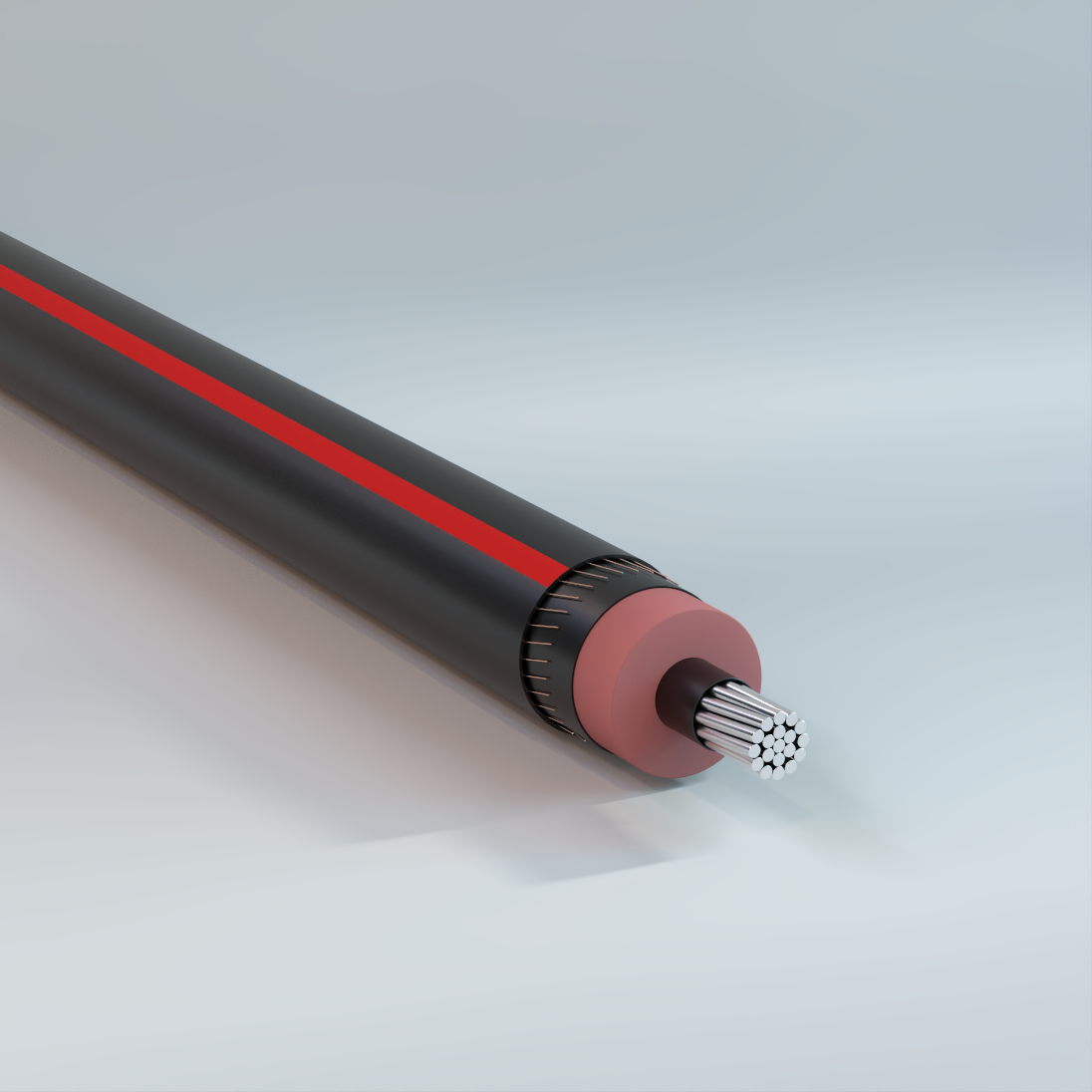
Primary UD
Underground, EPR Insulation, LLDPE Jacket, Concentric Neutral, 5kV-35kV – Aluminum
Used for underground primary residential and commercial distribution circuits. May be used in wet or dry locations, installed in underground ducts or direct burial.
Physical Data
| 5 kV EPR Insulated | |||||||||||||||
|---|---|---|---|---|---|---|---|---|---|---|---|---|---|---|---|
| 1/3 Neutral | Full Neutral | ||||||||||||||
| Size AWG or kcmil |
Number of Strands |
Nominal OD Over Insulation |
Number of Wires |
Size | Jacket Thickness |
Approximate Outside Diameter |
Approximate Net Weight |
Size AWG or kcmil |
Number of Strands |
Nominal OD Over Insulation |
Number of Wires |
Size | Jacket Thickness |
Approximate Outside Diameter |
Approximate Net Weight |
| in | AWG | mil | in | lb/kft | in | AWG | mil | in | lb/kft | ||||||
| Copper 100% Insulation Level (90 mil) | |||||||||||||||
| 2 | 7 | 0.5 | 6 | 14 | 50 | 0.81 | 484 | 2 | 7 | 0.5 | 16 | 14 | 50 | 0.81 | 604 |
| 1 | 19 | 0.54 | 7 | 14 | 50 | 0.84 | 564 | 1 | 19 | 0.54 | 13 | 12 | 50 | 0.88 | 747 |
| 1/0 | 19 | 0.58 | 9 | 14 | 50 | 0.88 | 672 | 1/0 | 19 | 0.58 | 16 | 12 | 50 | 0.92 | 889 |
| 2/0 | 19 | 0.63 | 11 | 14 | 50 | 0.93 | 799 | 2/0 | 19 | 0.63 | 13 | 10 | 50 | 1 | 1109 |
| 3/0 | 19 | 0.68 | 14 | 14 | 50 | 0.98 | 963 | 3/0 | 19 | 0.68 | 16 | 10 | 50 | 1.05 | 1331 |
| 4/0 | 19 | 0.73 | 18 | 14 | 50 | 1.03 | 1170 | 4/0 | 19 | 0.73 | 16 | 9 | 50 | 1.14 | 1637 |
| 250 | 37 | 0.79 | 13 | 12 | 50 | 1.12 | 1366 | 250 | 37 | 0.79 | 25 | 10 | 50 | 1.17 | 1910 |
| 350 | 37 | 0.89 | 18 | 12 | 50 | 1.23 | 1815 | 350 | 37 | 0.89 | 22 | 8 | 50 | 1.32 | 2614 |
| 500 | 37 | 1.02 | 17 | 10 | 50 | 1.42 | 2569 | 500 | 37 | 1.02 | 31 | 8 | 50 | 1.47 | 3603 |
| 750 | 61 | 1.21 | 20 | 9 | 80 | 1.7 | 3773 | — | — | — | — | — | — | — | — |
| 1000 | 61 | 1.36 | 26 | 9 | 80 | 1.85 | 4854 | — | — | — | — | — | — | — | — |
| The above data are approximate and subject to normal manufacturing tolerances. Other sizes available upon request. | |||||||||||||||
| 8 kV EPR Insulated | |||||||||||||||
|---|---|---|---|---|---|---|---|---|---|---|---|---|---|---|---|
| 1/3 Neutral | Full Neutral | ||||||||||||||
| Size AWG or kcmil |
Number of Strands |
Nominal OD Over Insulation |
Number of Wires |
Size | Jacket Thickness |
Approximate Outside Diameter |
Approximate Net Weight |
Size AWG or kcmil |
Number of Strands |
Nominal OD Over Insulation |
Number of Wires |
Size | Jacket Thickness |
Approximate Outside Diameter |
Approximate Net Weight |
| in | AWG | mil | in | lb/kft | in | AWG | mil | in | lb/kft | ||||||
| Copper 100% Insulation Level (115 mil) | |||||||||||||||
| 2 | 7 | 0.55 | 6 | 14 | 50 | 0.86 | 517 | 2 | 7 | 0.55 | 16 | 14 | 50 | 0.86 | 637 |
| 1 | 19 | 0.59 | 7 | 14 | 50 | 0.9 | 598 | 1 | 19 | 0.59 | 13 | 12 | 50 | 0.93 | 782 |
| 1/0 | 19 | 0.63 | 9 | 14 | 50 | 0.94 | 708 | 1/0 | 19 | 0.63 | 16 | 12 | 50 | 0.97 | 926 |
| 2/0 | 19 | 0.68 | 11 | 14 | 50 | 0.98 | 837 | 2/0 | 19 | 0.68 | 13 | 10 | 50 | 1.06 | 1149 |
| 3/0 | 19 | 0.73 | 14 | 14 | 50 | 1.03 | 1003 | 3/0 | 19 | 0.73 | 16 | 10 | 50 | 1.11 | 1373 |
| 4/0 | 19 | 0.78 | 18 | 14 | 50 | 1.09 | 1212 | 4/0 | 19 | 0.78 | 16 | 9 | 50 | 1.19 | 1682 |
| 250 | 37 | 0.84 | 13 | 12 | 50 | 1.18 | 1412 | 250 | 37 | 0.84 | 25 | 10 | 50 | 1.22 | 1957 |
| 350 | 37 | 0.94 | 18 | 12 | 50 | 1.28 | 1865 | 350 | 37 | 0.94 | 22 | 8 | 50 | 1.37 | 2667 |
| 500 | 37 | 1.07 | 17 | 10 | 50 | 1.47 | 2627 | 500 | 37 | 1.07 | 31 | 8 | 50 | 1.53 | 3663 |
| 750 | 61 | 1.26 | 20 | 9 | 80 | 1.75 | 3841 | — | — | — | — | — | — | — | — |
| 1000 | 61 | 1.41 | 26 | 9 | 80 | 1.9 | 4929 | — | — | — | — | — | — | — | — |
| The above data are approximate and subject to normal manufacturing tolerances. Other sizes available upon request. | |||||||||||||||
| 15 kV EPR Insulated | |||||||||||||||
|---|---|---|---|---|---|---|---|---|---|---|---|---|---|---|---|
| 1/3 Neutral | Full Neutral | ||||||||||||||
| Size AWG or kcmil |
Number of Strands |
Nominal OD Over Insulation |
Number of Wires |
Size | Jacket Thickness |
Approximate Outside Diameter |
Approximate Net Weight |
Size AWG or kcmil |
Number of Strands |
Nominal OD Over Insulation |
Number of Wires |
Size | Jacket Thickness |
Approximate Outside Diameter |
Approximate Net Weight |
| in | AWG | mil | in | lb/kft | in | AWG | mil | in | lb/kft | ||||||
| Copper 100% Insulation Level (175 mil) | |||||||||||||||
| 2 | 7 | 0.68 | 6 | 14 | 50 | 0.98 | 604 | 2 | 7 | 0.68 | 16 | 14 | 50 | 0.98 | 725 |
| 1 | 19 | 0.71 | 7 | 14 | 50 | 1.02 | 689 | 1 | 19 | 0.71 | 13 | 12 | 50 | 1.05 | 876 |
| 1/0 | 19 | 0.75 | 9 | 14 | 50 | 1.06 | 803 | 1/0 | 19 | 0.75 | 16 | 12 | 50 | 1.09 | 1024 |
| 2/0 | 19 | 0.8 | 11 | 14 | 50 | 1.1 | 937 | 2/0 | 19 | 0.8 | 13 | 10 | 50 | 1.18 | 1255 |
| 3/0 | 19 | 0.85 | 14 | 14 | 50 | 1.15 | 1108 | 3/0 | 19 | 0.85 | 16 | 10 | 50 | 1.23 | 1484 |
| 4/0 | 19 | 0.9 | 18 | 14 | 50 | 1.21 | 1323 | 4/0 | 19 | 0.9 | 16 | 9 | 50 | 1.31 | 1801 |
| 250 | 37 | 0.96 | 13 | 12 | 50 | 1.3 | 1531 | 250 | 37 | 0.96 | 25 | 10 | 50 | 1.34 | 2079 |
| 350 | 37 | 1.06 | 18 | 12 | 50 | 1.42 | 2019 | 350 | 37 | 1.06 | 22 | 8 | 50 | 1.52 | 2830 |
| 500 | 37 | 1.19 | 17 | 10 | 50 | 1.59 | 2775 | 500 | 37 | 1.19 | 31 | 8 | 80 | 1.71 | 3881 |
| 750 | 61 | 1.38 | 20 | 9 | 80 | 1.87 | 4015 | — | — | — | — | — | — | — | — |
| 1000 | 61 | 1.53 | 26 | 9 | 80 | 2.05 | 5167 | — | — | — | — | — | — | — | — |
| Aluminum 100% Insulation Level (175 mil) | |||||||||||||||
| 2 | 1 | 0.65 | 6 | 14 | 50 | 0.95 | 441 | 2 | 1 | 0.65 | 10 | 14 | 50 | 0.95 | 489 |
| 2 | 7 | 0.67 | 6 | 14 | 50 | 0.98 | 459 | 2 | 7 | 0.67 | 10 | 14 | 50 | 0.98 | 507 |
| 1 | 19 | 0.71 | 6 | 14 | 50 | 1.02 | 495 | 1 | 19 | 0.71 | 13 | 14 | 50 | 1.02 | 580 |
| 1/0 | 1 | 0.72 | 6 | 14 | 50 | 1.02 | 512 | 1/0 | 1 | 0.72 | 16 | 14 | 50 | 1.02 | 632 |
| 1/0 | 19 | 0.75 | 6 | 14 | 50 | 1.06 | 537 | 1/0 | 19 | 0.75 | 16 | 14 | 50 | 1.06 | 658 |
| 2/0 | 19 | 0.8 | 7 | 14 | 50 | 1.1 | 600 | 2/0 | 19 | 0.8 | 20 | 14 | 50 | 1.1 | 757 |
| 3/0 | 19 | 0.85 | 9 | 14 | 50 | 1.15 | 684 | 2/0 | 19 | 0.8 | 13 | 12 | 50 | 1.13 | 788 |
| 4/0 | 19 | 0.9 | 11 | 14 | 50 | 1.21 | 781 | 3/0 | 19 | 0.85 | 25 | 14 | 50 | 1.15 | 877 |
| 250 | 37 | 0.96 | 13 | 14 | 50 | 1.26 | 871 | 3/0 | 19 | 0.85 | 16 | 12 | 50 | 1.18 | 907 |
| 300 | 37 | 1.01 | 15 | 14 | 50 | 1.34 | 994 | 4/0 | 19 | 0.9 | 32 | 14 | 50 | 1.21 | 1034 |
| 350 | 37 | 1.06 | 18 | 14 | 50 | 1.39 | 1106 | 4/0 | 19 | 0.9 | 20 | 12 | 50 | 1.24 | 1058 |
| 500 | 37 | 1.19 | 25 | 14 | 50 | 1.52 | 1403 | 4/0 | 19 | 0.9 | 13 | 10 | 50 | 1.28 | 1104 |
| 500 | 37 | 1.19 | 16 | 12 | 50 | 1.55 | 1441 | 250 | 37 | 0.96 | 25 | 12 | 50 | 1.3 | 1220 |
| 750 | 61 | 1.4 | 24 | 12 | 80 | 1.82 | 2033 | 250 | 37 | 0.96 | 16 | 10 | 50 | 1.34 | 1264 |
| 750 | 61 | 1.4 | 15 | 10 | 80 | 1.86 | 2079 | 350 | 37 | 1.06 | 32 | 12 | 50 | 1.42 | 1532 |
| 1000 | 61 | 1.54 | 31 | 12 | 80 | 2 | 2544 | 350 | 37 | 1.06 | 20 | 10 | 50 | 1.46 | 1567 |
| 1000 | 61 | 1.54 | 20 | 10 | 80 | 2.04 | 2614 | 350 | 37 | 1.06 | 16 | 9 | 50 | 1.49 | 1595 |
| 1000 | 61 | 1.54 | 16 | 9 | 80 | 2.07 | 2651 | 500 | 37 | 1.19 | 29 | 10 | 50 | 1.59 | 2060 |
| — | — | — | — | — | — | — | — | 750 | 61 | 1.4 | 28 | 8 | 80 | 1.91 | 3043 |
| — | — | — | — | — | — | — | — | 1000 | 61 | 1.54 | 37 | 8 | 80 | 2.09 | 3868 |
| The above data are approximate and subject to normal manufacturing tolerances. Other sizes available upon request. | |||||||||||||||
| 15 kV EPR Insulated | |||||||||||||||
|---|---|---|---|---|---|---|---|---|---|---|---|---|---|---|---|
| 1/3 Neutral | Full Neutral | ||||||||||||||
| Size AWG or kcmil |
Number of Strands |
Nominal OD Over Insulation |
Number of Wires |
Size | Jacket Thickness |
Approximate Outside Diameter |
Approximate Net Weight |
Size AWG or kcmil |
Number of Strands |
Nominal OD Over Insulation |
Number of Wires |
Size | Jacket Thickness |
Approximate Outside Diameter |
Approximate Net Weight |
| in | AWG | mil | in | lb/kft | in | AWG | mil | in | lb/kft | ||||||
| Copper 133% Insulation Level (220 mil) | |||||||||||||||
| 2 | 7 | 0.77 | 6 | 14 | 50 | 1.07 | 678 | 2 | 7 | 0.77 | 16 | 14 | 50 | 1.07 | 798 |
| 1 | 19 | 0.81 | 7 | 14 | 50 | 1.11 | 766 | 1 | 19 | 0.81 | 13 | 12 | 50 | 1.14 | 955 |
| 1/0 | 19 | 0.85 | 9 | 14 | 50 | 1.15 | 883 | 1/0 | 19 | 0.85 | 16 | 12 | 50 | 1.18 | 1105 |
| 2/0 | 19 | 0.89 | 11 | 14 | 50 | 1.19 | 1020 | 2/0 | 19 | 0.89 | 13 | 10 | 50 | 1.27 | 1342 |
| 3/0 | 19 | 0.94 | 14 | 14 | 50 | 1.24 | 1195 | 3/0 | 19 | 0.94 | 16 | 10 | 50 | 1.32 | 1575 |
| 4/0 | 19 | 1 | 18 | 14 | 50 | 1.3 | 1414 | 4/0 | 19 | 1 | 16 | 9 | 50 | 1.4 | 1898 |
| 250 | 37 | 1.05 | 13 | 12 | 50 | 1.41 | 1653 | 250 | 37 | 1.05 | 25 | 10 | 50 | 1.46 | 2204 |
| 350 | 37 | 1.16 | 18 | 12 | 50 | 1.52 | 2126 | 350 | 37 | 1.16 | 22 | 8 | 50 | 1.61 | 2942 |
| 500 | 37 | 1.28 | 17 | 10 | 80 | 1.75 | 2962 | 500 | 37 | 1.28 | 31 | 8 | 80 | 1.8 | 4007 |
| 750 | 61 | 1.47 | 20 | 9 | 80 | 1.96 | 4154 | — | — | — | — | — | — | — | — |
| 1000 | 61 | 1.62 | 26 | 9 | 80 | 2.14 | 5320 | — | — | — | — | — | — | — | — |
| Aluminum 133% Insulation Level (220 mil) | |||||||||||||||
| 2 | 1 | 0.74 | 6 | 14 | 50 | 1.04 | 511 | 2 | 1 | 0.74 | 10 | 14 | 50 | 1.04 | 560 |
| 2 | 7 | 0.76 | 6 | 14 | 50 | 1.07 | 532 | 2 | 7 | 0.76 | 10 | 14 | 50 | 1.07 | 580 |
| 1 | 19 | 0.8 | 6 | 14 | 50 | 1.11 | 571 | 1 | 19 | 0.8 | 13 | 14 | 50 | 1.11 | 655 |
| 1/0 | 1 | 0.81 | 6 | 14 | 50 | 1.11 | 588 | 1/0 | 1 | 0.81 | 16 | 14 | 50 | 1.11 | 708 |
| 1/0 | 19 | 0.84 | 6 | 14 | 50 | 1.16 | 629 | 1/0 | 19 | 0.84 | 16 | 14 | 50 | 1.15 | 737 |
| 2/0 | 19 | 0.89 | 7 | 14 | 50 | 1.19 | 682 | 2/0 | 19 | 0.89 | 20 | 14 | 50 | 1.19 | 839 |
| 3/0 | 19 | 0.94 | 9 | 14 | 50 | 1.24 | 770 | 2/0 | 19 | 0.89 | 13 | 12 | 50 | 1.22 | 872 |
| 4/0 | 19 | 0.99 | 11 | 14 | 50 | 1.3 | 871 | 3/0 | 19 | 0.94 | 25 | 14 | 50 | 1.24 | 963 |
| 250 | 37 | 1.05 | 13 | 14 | 50 | 1.38 | 989 | 3/0 | 19 | 0.94 | 16 | 12 | 50 | 1.27 | 994 |
| 350 | 37 | 1.15 | 18 | 14 | 50 | 1.48 | 1209 | 4/0 | 19 | 0.99 | 32 | 14 | 50 | 1.3 | 1124 |
| 500 | 37 | 1.28 | 25 | 14 | 50 | 1.61 | 1517 | 4/0 | 19 | 0.99 | 20 | 12 | 50 | 1.33 | 1149 |
| 500 | 37 | 1.28 | 16 | 12 | 80 | 1.7 | 1623 | 4/0 | 19 | 0.99 | 13 | 10 | 50 | 1.37 | 1199 |
| 750 | 61 | 1.49 | 24 | 12 | 80 | 1.91 | 2167 | 250 | 37 | 1.05 | 25 | 12 | 50 | 1.41 | 1341 |
| 750 | 61 | 1.49 | 15 | 10 | 80 | 1.95 | 2216 | 250 | 37 | 1.05 | 16 | 10 | 50 | 1.45 | 1388 |
| 1000 | 61 | 1.64 | 31 | 12 | 80 | 2.09 | 2692 | 350 | 37 | 1.15 | 32 | 12 | 50 | 1.51 | 1637 |
| 1000 | 61 | 1.64 | 20 | 10 | 80 | 2.13 | 2764 | 350 | 37 | 1.15 | 20 | 10 | 50 | 1.55 | 1674 |
| 1000 | 61 | 1.64 | 16 | 9 | 80 | 2.16 | 2803 | 350 | 37 | 1.15 | 16 | 9 | 50 | 1.58 | 1704 |
| The above data are approximate and subject to normal manufacturing tolerances. Other sizes available upon request. | |||||||||||||||
| 25 kV EPR Insulated | |||||||||||||||
|---|---|---|---|---|---|---|---|---|---|---|---|---|---|---|---|
| 1/3 Neutral | Full Neutral | ||||||||||||||
| Size AWG or kcmil |
Number of Strands |
Nominal OD Over Insulation |
Number of Wires |
Size | Jacket Thickness |
Approximate Outside Diameter |
Approximate Net Weight |
Size AWG or kcmil |
Number of Strands |
Nominal OD Over Insulation |
Number of Wires |
Size | Jacket Thickness |
Approximate Outside Diameter |
Approximate Net Weight |
| in | AWG | mil | in | lb/kft | in | AWG | mil | in | lb/kft | ||||||
| Copper 100% Insulation Level (260 mil) | |||||||||||||||
| 1 | 19 | 0.89 | 7 | 14 | 50 | 1.19 | 840 | 1 | 19 | 0.89 | 13 | 12 | 50 | 1.23 | 1030 |
| 1/0 | 19 | 0.93 | 9 | 14 | 50 | 1.23 | 959 | 1/0 | 19 | 0.93 | 16 | 12 | 50 | 1.27 | 1184 |
| 2/0 | 19 | 0.97 | 11 | 14 | 50 | 1.28 | 1099 | 2/0 | 19 | 0.97 | 13 | 10 | 50 | 1.35 | 1426 |
| 3/0 | 19 | 1.02 | 14 | 14 | 50 | 1.35 | 1301 | 3/0 | 19 | 1.02 | 16 | 10 | 50 | 1.42 | 1687 |
| 4/0 | 19 | 1.08 | 18 | 14 | 50 | 1.4 | 1525 | 4/0 | 19 | 1.08 | 16 | 9 | 50 | 1.51 | 2016 |
| 250 | 37 | 1.13 | 13 | 12 | 50 | 1.49 | 1747 | 250 | 37 | 1.13 | 25 | 10 | 50 | 1.54 | 2300 |
| 350 | 37 | 1.24 | 18 | 12 | 50 | 1.6 | 2227 | 350 | 37 | 1.24 | 22 | 8 | 80 | 1.75 | 3116 |
| 500 | 37 | 1.37 | 17 | 10 | 80 | 1.83 | 3077 | 500 | 37 | 1.37 | 31 | 8 | 80 | 1.88 | 4124 |
| 750 | 61 | 1.56 | 20 | 9 | 80 | 2.08 | 4333 | — | — | — | — | — | — | — | — |
| 1000 | 61 | 1.7 | 26 | 9 | 80 | 2.23 | 5461 | — | — | — | — | — | — | — | — |
| Aluminum 100% Insulation Level (260 mil) | |||||||||||||||
| 1 | 19 | 0.88 | 6 | 14 | 50 | 1.19 | 644 | 1 | 19 | 0.88 | 13 | 14 | 50 | 1.19 | 728 |
| 1/0 | 1 | 0.89 | 6 | 14 | 50 | 1.19 | 661 | 1/0 | 1 | 0.89 | 16 | 14 | 50 | 1.19 | 781 |
| 1/0 | 19 | 0.92 | 6 | 14 | 50 | 1.23 | 692 | 1/0 | 19 | 0.92 | 16 | 14 | 50 | 1.23 | 812 |
| 2/0 | 19 | 0.97 | 7 | 14 | 50 | 1.27 | 760 | 2/0 | 19 | 0.97 | 20 | 14 | 50 | 1.27 | 917 |
| 3/0 | 19 | 1.02 | 9 | 14 | 50 | 1.34 | 875 | 2/0 | 19 | 0.97 | 13 | 12 | 50 | 1.3 | 952 |
| 4/0 | 19 | 1.07 | 11 | 14 | 50 | 1.4 | 981 | 3/0 | 19 | 1.02 | 25 | 14 | 50 | 1.34 | 1068 |
| 250 | 37 | 1.13 | 13 | 14 | 50 | 1.46 | 1080 | 3/0 | 19 | 1.02 | 16 | 12 | 50 | 1.38 | 1102 |
| 350 | 37 | 1.23 | 18 | 14 | 50 | 1.56 | 1307 | 4/0 | 19 | 1.07 | 32 | 14 | 50 | 1.4 | 1234 |
| 500 | 37 | 1.36 | 25 | 14 | 80 | 1.75 | 1692 | 4/0 | 19 | 1.07 | 20 | 12 | 50 | 1.43 | 1261 |
| 500 | 37 | 1.36 | 16 | 12 | 80 | 1.78 | 1735 | 4/0 | 19 | 1.07 | 13 | 10 | 50 | 1.48 | 1313 |
| 750 | 61 | 1.57 | 24 | 12 | 80 | 2.02 | 2340 | 250 | 37 | 1.13 | 25 | 12 | 50 | 1.49 | 1433 |
| 750 | 61 | 1.57 | 15 | 10 | 80 | 2.06 | 2392 | 250 | 37 | 1.13 | 16 | 10 | 50 | 1.53 | 1482 |
| 1000 | 61 | 1.72 | 31 | 12 | 80 | 2.17 | 2829 | 350 | 37 | 1.23 | 32 | 12 | 50 | 1.59 | 1736 |
| 1000 | 61 | 1.72 | 20 | 10 | 80 | 2.21 | 2903 | 350 | 37 | 1.23 | 20 | 10 | 80 | 1.7 | 1843 |
| 1000 | 61 | 1.72 | 16 | 9 | 80 | 2.24 | 2944 | 350 | 37 | 1.23 | 16 | 9 | 80 | 1.72 | 1875 |
| — | — | — | — | — | — | — | — | 500 | 37 | 1.36 | 29 | 10 | 80 | 1.83 | 2361 |
| — | — | — | — | — | — | — | — | 750 | 61 | 1.57 | 28 | 8 | 80 | 2.12 | 3362 |
| — | — | — | — | — | — | — | — | 1000 | 61 | 1.72 | 37 | 8 | 80 | 2.27 | 4163 |
| 1000 | 61 | 1.54 | 20 | 10 | 80 | 2.04 | 2614 | 37 | 1.06 | 9 | 50 | 1.49 | 1595 | ||
| 1000 | 61 | 1.54 | 16 | 9 | 80 | 2.07 | 2651 | 37 | 1.19 | 10 | 50 | 1.59 | 2060 | ||
| — | — | — | — | — | — | — | — | 61 | 1.4 | 8 | 80 | 1.91 | 3043 | ||
| — | — | — | — | — | — | — | — | 61 | 1.54 | 8 | 80 | 2.09 | 3868 | ||
| The above data are approximate and subject to normal manufacturing tolerances. Other sizes available upon request. | |||||||||||||||
| 25 kV EPR Insulated | |||||||||||||||
|---|---|---|---|---|---|---|---|---|---|---|---|---|---|---|---|
| 1/3 Neutral | Full Neutral | ||||||||||||||
| Size AWG or kcmil |
Number of Strands |
Nominal OD Over Insulation |
Number of Wires |
Size | Jacket Thickness |
Approximate Outside Diameter |
Approximate Net Weight |
Size AWG or kcmil |
Number of Strands |
Nominal OD Over Insulation |
Number of Wires |
Size | Jacket Thickness |
Approximate Outside Diameter |
Approximate Net Weight |
| in | AWG | mil | in | lb/kft | in | AWG | mil | in | lb/kft | ||||||
| Copper 133% Insulation Level (320 mil) | |||||||||||||||
| 1 | 19 | 1.01 | 7 | 14 | 50 | 1.31 | 961 | 1 | 19 | 1.01 | 13 | 12 | 50 | 1.35 | 1154 |
| 1/0 | 19 | 1.05 | 9 | 14 | 50 | 1.38 | 1109 | 1/0 | 19 | 1.05 | 16 | 12 | 50 | 1.41 | 1337 |
| 2/0 | 19 | 1.09 | 11 | 14 | 50 | 1.42 | 1254 | 2/0 | 19 | 1.09 | 13 | 10 | 50 | 1.5 | 1588 |
| 3/0 | 19 | 1.14 | 14 | 14 | 50 | 1.47 | 1439 | 3/0 | 19 | 1.14 | 16 | 10 | 50 | 1.55 | 1830 |
| 4/0 | 19 | 1.2 | 18 | 14 | 50 | 1.53 | 1668 | 4/0 | 19 | 1.2 | 16 | 9 | 80 | 1.69 | 2232 |
| 250 | 37 | 1.26 | 13 | 12 | 50 | 1.62 | 1898 | 250 | 37 | 1.26 | 25 | 10 | 80 | 1.72 | 2522 |
| 350 | 37 | 1.36 | 18 | 12 | 80 | 1.78 | 2458 | 350 | 37 | 1.36 | 22 | 8 | 80 | 1.88 | 3290 |
| 500 | 37 | 1.49 | 17 | 10 | 80 | 1.95 | 3260 | 500 | 37 | 1.49 | 31 | 8 | 80 | 2.01 | 4311 |
| 750 | 61 | 1.68 | 20 | 9 | 80 | 2.2 | 4540 | — | — | — | — | — | — | — | — |
| 1000 | 61 | 1.83 | 26 | 9 | 80 | 2.35 | 5683 | — | — | — | — | — | — | — | — |
| Aluminum 133% Insulation Level (320 mil) | |||||||||||||||
| 1/0 | 19 | 1.05 | 6 | 14 | 50 | 1.37 | 839 | 1/0 | 19 | 1.05 | 16 | 14 | 50 | 1.37 | 959 |
| 2/0 | 19 | 1.09 | 7 | 14 | 50 | 1.42 | 913 | 2/0 | 19 | 1.09 | 20 | 14 | 50 | 1.42 | 1070 |
| 3/0 | 19 | 1.14 | 9 | 14 | 50 | 1.47 | 1010 | 2/0 | 19 | 1.09 | 13 | 12 | 50 | 1.45 | 1108 |
| 4/0 | 19 | 1.2 | 11 | 14 | 50 | 1.52 | 1122 | 3/0 | 19 | 1.14 | 25 | 14 | 50 | 1.47 | 1203 |
| 250 | 37 | 1.25 | 13 | 14 | 50 | 1.58 | 1226 | 3/0 | 19 | 1.14 | 16 | 12 | 50 | 1.5 | 1239 |
| 350 | 37 | 1.35 | 18 | 14 | 80 | 1.74 | 1533 | 4/0 | 19 | 1.2 | 32 | 14 | 50 | 1.52 | 1375 |
| 500 | 37 | 1.48 | 25 | 14 | 80 | 1.87 | 1867 | 4/0 | 19 | 1.2 | 20 | 12 | 50 | 1.55 | 1405 |
| 500 | 37 | 1.48 | 16 | 12 | 80 | 1.91 | 1912 | 4/0 | 19 | 1.2 | 13 | 10 | 50 | 1.6 | 1460 |
| 750 | 61 | 1.69 | 24 | 12 | 80 | 2.14 | 2540 | 250 | 37 | 1.25 | 25 | 12 | 50 | 1.61 | 1583 |
| 750 | 61 | 1.69 | 15 | 10 | 80 | 2.18 | 2596 | 250 | 37 | 1.25 | 16 | 10 | 80 | 1.72 | 1703 |
| 1000 | 61 | 1.84 | 31 | 12 | 80 | 2.29 | 3045 | 350 | 37 | 1.35 | 32 | 12 | 80 | 1.78 | 1966 |
| 1000 | 61 | 1.84 | 20 | 10 | 80 | 2.33 | 3123 | 350 | 37 | 1.35 | 20 | 10 | 80 | 1.82 | 2011 |
| 1000 | 61 | 1.84 | 16 | 9 | 80 | 2.36 | 3165 | 350 | 37 | 1.35 | 16 | 9 | 80 | 1.84 | 2045 |
| — | — | — | — | — | — | — | — | 500 | 37 | 1.48 | 29 | 10 | 80 | 1.95 | 2541 |
| 1000 | 61 | 1.72 | 10 | 80 | 2.21 | 2903 | 350 | 1.23 | 20 | 10 | 1.7 | 1843 | — | — | — |
| 1000 | 61 | 1.72 | 9 | 80 | 2.24 | 2944 | 350 | 1.23 | 16 | 9 | 1.72 | 1875 | — | — | — |
| — | — | — | — | — | — | — | 500 | 1.36 | 29 | 10 | 1.83 | 2361 | — | — | — |
| — | — | — | — | — | — | — | 750 | 1.57 | 28 | 8 | 2.12 | 3362 | — | — | — |
| — | — | — | — | — | — | — | 1000 | 1.72 | 37 | 8 | 2.27 | 4163 | — | — | — |
| 1000 | 61 | 1.54 | 10 | 80 | 2.04 | 2614 | 37 | — | 9 | 50 | 1595 | — | — | — | — |
| 1000 | 61 | 1.54 | 9 | 80 | 2.07 | 2651 | 37 | — | 10 | 50 | 2060 | — | — | — | — |
| — | — | — | — | — | — | — | 61 | — | 8 | 80 | 3043 | — | — | — | — |
| — | — | — | — | — | — | — | 61 | — | 8 | 80 | 3868 | — | — | — | — |
| The above data are approximate and subject to normal manufacturing tolerances. Other sizes available upon request. | |||||||||||||||
| 35 kV EPR Insulated | |||||||||||||||
|---|---|---|---|---|---|---|---|---|---|---|---|---|---|---|---|
| 1/3 Neutral | Full Neutral | ||||||||||||||
| Size AWG or kcmil |
Number of Strands |
Nominal OD Over Insulation |
Number of Wires |
Size | Jacket Thickness |
Approximate Outside Diameter |
Approximate Net Weight |
Size AWG or kcmil |
Number of Strands |
Nominal OD Over Insulation |
Number of Wires |
Size | Jacket Thickness |
Approximate Outside Diameter |
Approximate Net Weight |
| in | AWG | mil | in | lb/kft | i n | AWG | mil | in | lb/kft | ||||||
| Copper 100% Insulation Level (345 mil) | |||||||||||||||
| 1/0 | 19 | 1.1 | 9 | 14 | 50 | 1.43 | 1166 | 1/0 | 19 | 1.1 | 16 | 12 | 50 | 1.46 | 1395 |
| 2/0 | 19 | 1.15 | 11 | 14 | 50 | 1.47 | 1313 | 2/0 | 19 | 1.15 | 13 | 10 | 50 | 1.55 | 1649 |
| 3/0 | 19 | 1.2 | 14 | 14 | 50 | 1.52 | 1499 | 3/0 | 19 | 1.2 | 16 | 10 | 50 | 1.6 | 1893 |
| 4/0 | 19 | 1.25 | 18 | 14 | 50 | 1.58 | 1731 | 4/0 | 19 | 1.25 | 16 | 9 | 80 | 1.74 | 2301 |
| 250 | 37 | 1.31 | 13 | 12 | 80 | 1.73 | 2032 | 250 | 37 | 1.31 | 25 | 10 | 80 | 1.77 | 2592 |
| 350 | 37 | 1.41 | 18 | 12 | 80 | 1.83 | 2531 | 350 | 37 | 1.41 | 22 | 8 | 80 | 1.93 | 3366 |
| 500 | 37 | 1.54 | 17 | 10 | 80 | 2.04 | 3388 | 500 | 37 | 1.54 | 31 | 8 | 80 | 2.09 | 4443 |
| 750 | 61 | 1.73 | 20 | 9 | 80 | 2.25 | 4630 | — | — | — | — | — | — | — | — |
| 1000 | 61 | 1.88 | 26 | 9 | 80 | 2.4 | 5779 | — | — | — | — | — | — | — | — |
| Aluminum 100% Insulation Level (345 mil) | |||||||||||||||
| 1/0 | 1 | 1.06 | 6 | 14 | 50 | 1.38 | 858 | 1/0 | 1 | 1.06 | 16 | 14 | 50 | 1.38 | 979 |
| 1/0 | 19 | 1.1 | 6 | 14 | 50 | 1.42 | 895 | 1/0 | 19 | 1.1 | 16 | 14 | 50 | 1.42 | 1015 |
| 2/0 | 19 | 1.14 | 7 | 14 | 50 | 1.47 | 971 | 2/0 | 19 | 1.14 | 20 | 14 | 50 | 1.47 | 1127 |
| 3/0 | 19 | 1.19 | 9 | 14 | 50 | 1.52 | 1070 | 2/0 | 19 | 1.14 | 13 | 12 | 50 | 1.5 | 1167 |
| 4/0 | 19 | 1.25 | 11 | 14 | 50 | 1.57 | 1184 | 3/0 | 19 | 1.19 | 25 | 14 | 50 | 1.52 | 1263 |
| 250 | 37 | 1.3 | 13 | 14 | 80 | 1.69 | 1358 | 3/0 | 19 | 1.19 | 16 | 12 | 50 | 1.55 | 1300 |
| 350 | 37 | 1.4 | 18 | 14 | 80 | 1.79 | 1604 | 4/0 | 19 | 1.25 | 32 | 14 | 50 | 1.57 | 1437 |
| 500 | 37 | 1.53 | 25 | 14 | 80 | 1.95 | 1989 | 4/0 | 19 | 1.25 | 20 | 12 | 50 | 1.61 | 1468 |
| 500 | 37 | 1.53 | 16 | 12 | 80 | 1.99 | 2036 | 4/0 | 19 | 1.25 | 13 | 10 | 80 | 1.71 | 1592 |
| 750 | 61 | 1.74 | 24 | 12 | 80 | 2.19 | 2628 | 250 | 37 | 1.3 | 25 | 12 | 80 | 1.73 | 1716 |
| 750 | 61 | 1.74 | 15 | 10 | 80 | 2.24 | 2684 | 250 | 37 | 1.3 | 16 | 10 | 80 | 1.77 | 1772 |
| 1000 | 61 | 1.89 | 31 | 12 | 80 | 2.34 | 3139 | 350 | 37 | 1.4 | 32 | 12 | 80 | 1.83 | 2038 |
| 1000 | 61 | 1.89 | 20 | 10 | 80 | 2.38 | 3217 | 350 | 37 | 1.4 | 20 | 10 | 80 | 1.87 | 2084 |
| 1000 | 61 | 1.89 | 16 | 9 | 80 | 2.41 | 3260 | 350 | 37 | 1.4 | 16 | 9 | 80 | 1.89 | 2119 |
| — | — | — | — | — | — | — | — | 500 | 37 | 1.53 | 29 | 10 | 80 | 2.03 | 2667 |
| — | — | — | — | — | — | — | — | 750 | 61 | 1.74 | 28 | 8 | 80 | 2.29 | 3661 |
| — | — | — | — | — | — | — | — | 1000 | 61 | 1.89 | 37 | 8 | 80 | 2.44 | 4483 |
| 1000 | 61 | 1.72 | 80 | 2.24 | 2944 | 350 | 1.23 | 9 | 1.72 | 1875 | — | — | — | — | — |
| — | — | — | — | — | — | 500 | 1.36 | 10 | 1.83 | 2361 | — | — | — | — | — |
| — | — | — | — | — | — | 750 | 1.57 | 8 | 2.12 | 3362 | — | — | — | — | — |
| — | — | — | — | — | — | 1000 | 1.72 | 8 | 2.27 | 4163 | — | — | — | — | — |
| 1000 | 61 | 1.54 | 80 | 2.04 | 2614 | 37 | 50 | 1595 | — | — | — | — | — | — | |
| 1000 | 61 | 1.54 | 80 | 2.07 | 2651 | 37 | 50 | 2060 | — | — | — | — | — | — | |
| — | — | — | — | — | — | 61 | 80 | 3043 | — | — | — | — | — | — | |
| — | — | — | — | — | — | 61 | 80 | 3868 | — | — | — | — | — | — | |
| The above data are approximate and subject to normal manufacturing tolerances. Other sizes available upon request. | |||||||||||||||
| 35 kV EPR Insulated | |||||||||||||||
|---|---|---|---|---|---|---|---|---|---|---|---|---|---|---|---|
| 1/3 Neutral | Full Neutral | ||||||||||||||
| Size AWG or kcmil |
Number of Strands |
Nominal OD Over Insulation |
Number of Wires |
Size | Jacket Thickness |
Approximate Outside Diameter |
Approximate Net Weight |
Size AWG or kcmil |
Number of Strands |
Nominal OD Over Insulation |
Number of Wires |
Size | Jacket Thickness |
Approximate Outside Diameter |
Approximate Net Weight |
| i n | AWG | mil | in | lb/kft | i n | AWG | mil | in | lb/kft | ||||||
| Copper 133% Insulation Level (420 mil) | |||||||||||||||
| 1/0 | 19 | 1.25 | 9 | 14 | 50 | 1.58 | 1349 | 1/0 | 19 | 1.25 | 16 | 12 | 50 | 1.61 | 1581 |
| 2/0 | 19 | 1.3 | 11 | 14 | 50 | 1.63 | 1502 | 2/0 | 19 | 1.3 | 13 | 10 | 80 | 1.76 | 1914 |
| 3/0 | 19 | 1.35 | 14 | 14 | 80 | 1.74 | 1762 | 3/0 | 19 | 1.35 | 16 | 10 | 80 | 1.81 | 2166 |
| 4/0 | 19 | 1.4 | 18 | 14 | 80 | 1.79 | 2004 | 4/0 | 19 | 1.4 | 16 | 9 | 80 | 1.89 | 2519 |
| 250 | 37 | 1.46 | 13 | 12 | 80 | 1.88 | 2251 | 250 | 37 | 1.46 | 25 | 10 | 80 | 1.93 | 2815 |
| 350 | 37 | 1.56 | 18 | 12 | 80 | 2.02 | 2811 | 350 | 37 | 1.56 | 22 | 8 | 80 | 2.11 | 3658 |
| 500 | 37 | 1.69 | 17 | 10 | 80 | 2.19 | 3645 | 500 | 37 | 1.69 | 31 | 8 | 80 | 2.24 | 4704 |
| 750 | 61 | 1.88 | 20 | 9 | 80 | 2.4 | 4912 | — | — | — | — | — | — | — | — |
| 1000 | 61 | 2.03 | 26 | 9 | 80 | 2.55 | 6081 | — | — | — | — | — | — | — | — |
| Aluminum 133% Insulation Level (420 mil) | |||||||||||||||
| 1/0 | 19 | 1.25 | 6 | 14 | 50 | 1.57 | 1076 | 1/0 | 19 | 1.25 | 16 | 14 | 50 | 1.57 | 1196 |
| 2/0 | 19 | 1.29 | 7 | 14 | 50 | 1.62 | 1157 | 2/0 | 19 | 1.29 | 20 | 14 | 80 | 1.68 | 1380 |
| 3/0 | 19 | 1.34 | 9 | 14 | 80 | 1.73 | 1331 | 2/0 | 19 | 1.29 | 13 | 12 | 80 | 1.71 | 1424 |
| 4/0 | 19 | 1.4 | 11 | 14 | 80 | 1.79 | 1454 | 3/0 | 19 | 1.34 | 25 | 14 | 80 | 1.73 | 1524 |
| 250 | 37 | 1.45 | 13 | 14 | 80 | 1.84 | 1571 | 3/0 | 19 | 1.34 | 16 | 12 | 80 | 1.76 | 1566 |
| 350 | 37 | 1.56 | 18 | 14 | 80 | 1.98 | 1876 | 4/0 | 19 | 1.4 | 32 | 14 | 80 | 1.79 | 1707 |
| 500 | 37 | 1.68 | 25 | 14 | 80 | 2.11 | 2235 | 4/0 | 19 | 1.4 | 20 | 12 | 80 | 1.82 | 1743 |
| 500 | 37 | 1.68 | 16 | 12 | 80 | 2.14 | 2285 | 4/0 | 19 | 1.4 | 13 | 10 | 80 | 1.86 | 1805 |
| 750 | 61 | 1.89 | 24 | 12 | 80 | 2.34 | 2902 | 250 | 37 | 1.45 | 25 | 12 | 80 | 1.88 | 1933 |
| 750 | 61 | 1.89 | 15 | 10 | 80 | 2.39 | 2963 | 250 | 37 | 1.45 | 16 | 10 | 80 | 1.92 | 1992 |
| 1000 | 61 | 2.04 | 16 | 9 | 80 | 2.56 | 3560 | 350 | 37 | 1.56 | 32 | 12 | 80 | 2.01 | 2314 |
| — | — | — | — | — | — | — | — | 350 | 37 | 1.56 | 20 | 10 | 80 | 2.05 | 2365 |
| — | — | — | — | — | — | — | — | 350 | 37 | 1.56 | 16 | 9 | 80 | 2.08 | 2403 |
| — | — | — | — | — | — | — | — | 500 | 37 | 1.68 | 29 | 10 | 80 | 2.18 | 2920 |
| 1000 | 61 | 1.89 | 9 | 80 | 2.41 | 3260 | 350 | 1.4 | 16 | 9 | 1.89 | 2119 | — | — | — |
| — | — | — | — | — | — | — | 500 | 1.53 | 29 | 10 | 2.03 | 2667 | — | — | — |
| — | — | — | — | — | — | — | 750 | 1.74 | 28 | 8 | 2.29 | 3661 | — | — | — |
| — | — | — | — | — | — | — | 1000 | 1.89 | 37 | 8 | 2.44 | 4483 | — | — | — |
| 1000 | 61 | 1.72 | 2.24 | 2944 | 350 | 1.23 | 9 | 1875 | — | — | — | — | — | — | — |
| — | — | — | — | — | 500 | 1.36 | 10 | 2361 | — | — | — | — | — | — | — |
| — | — | — | — | — | 750 | 1.57 | 8 | 3362 | — | — | — | — | — | — | — |
| — | — | — | — | — | 1000 | 1.72 | 8 | 4163 | — | — | — | — | — | — | — |
| 1000 | 61 | 1.54 | 2.04 | 2614 | 37 | — | 50 | — | — | — | — | — | — | — | — |
| 1000 | 61 | 1.54 | 2.07 | 2651 | 37 | — | 50 | — | — | — | — | — | — | — | — |
| — | — | — | — | — | 61 | — | 80 | — | — | — | — | — | — | — | — |
| — | — | — | — | — | 61 | — | 80 | — | — | — | — | — | — | — | — |
| The above data are approximate and subject to normal manufacturing tolerances. Other sizes available upon request. | |||||||||||||||
Ampacity Data
| Ampacity 100% and 133% Insulation Levels | ||||||||
|---|---|---|---|---|---|---|---|---|
| Size AWG or kcmil |
Copper | Aluminum | ||||||
| 5 – 15 kV | 25 – 46 kV | 5 – 15 kV | 25 – 46 kV | |||||
| 1/3 Neutral | Full Neutral | 1/3 Neutral | Full Neutral | 1/3 Neutral | Full Neutral | 1/3 Neutral | Full Neutral | |
| amp | amp | amp | amp | |||||
| 2 | 160 | 160 | – | – | 125 | 125 | – | – |
| 1 | 187 | 185 | 189 | 188 | 146 | 145 | 147 | 147 |
| 1/0 | 212 | 210 | 214 | 212 | 166 | 165 | 167 | 167 |
| 2/0 | 241 | 238 | 248 | 245 | 189 | 188 | 194 | 193 |
| 3/0 | 273 | 268 | 281 | 276 | 214 | 213 | 220 | 218 |
| 4/0 | 309 | 300 | 317 | 309 | 244 | 241 | 250 | 247 |
| 250 | 336 | – | 344 | – | 266 | – | 273 | – |
| 350 | 398 | – | 407 | – | 320 | – | 326 | – |
| 500 | 476 | – | 476 | – | 394 | – | 392 | – |
| 750 | 547 | – | 565 | – | 476 | – | 486 | – |
| 1000 | 620 | – | 625 | – | 550 | – | 556 | – |
– |
1/6 Neutral | Full Neutral | 1/6 Neutral | Full Neutral | 1/6 Neutral | Full Neutral | 1/6 Neutral | Full Neutral |
| 1000 | 658 | – | 658 | – | 580 | – | 573 | – |
| † Ampacities are based on the following: Copper: Three shielded single insulated Copper conductors in buried ducts, single circuit, 25 °C ambient earth temperature, 75% load factor, 90 RHO and 90 °C conductor temperature (IEEE Std. 835). Aluminum: Three shielded single insulated Aluminum conductors in buried ducts, single circuit, 25 °C ambient earth temperature, 75% load factor, 90 RHO and 90 °C conductor temperature (IEEE Std. 835). |
||||||||
| Rating Voltage |
Minimum Size AWG |
|---|---|
| 5 kV | 8 |
| 8 kV | 6 |
| 15 kV | 2 |
| 25 kV | 1 |
| 35 kV | 1/0 |
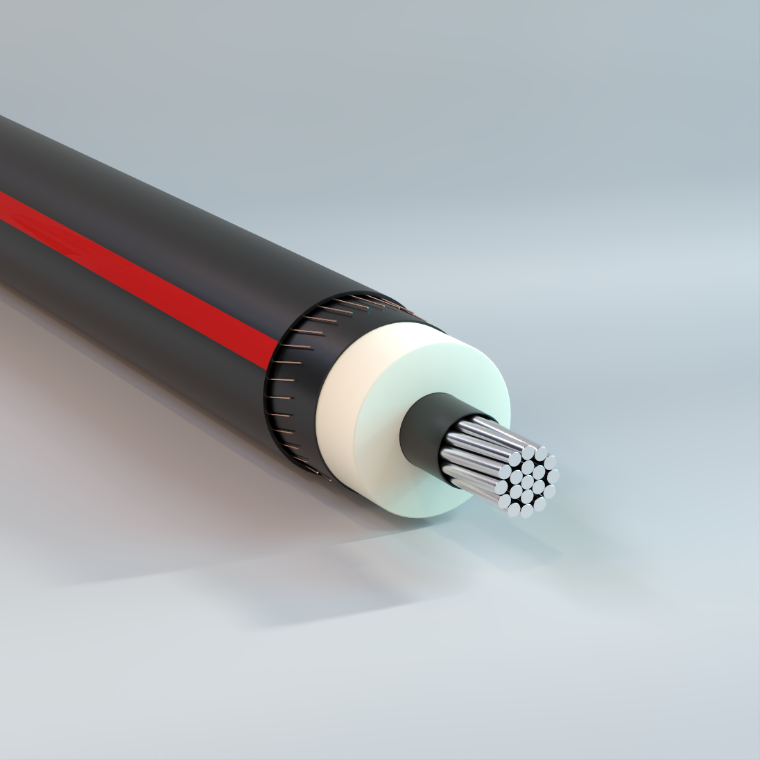
Primary UD
Underground, TR-XLPE Insulation, XLPE Jacket, Full or Reduced Concentric Neutral, 35kV Renewable Applications – Aluminum
Specifically designed for underground primary circuits in renewable projects in both solar and wind farms. May be used in wet or dry locations, installed in underground ducts or direct burial.
Physical Data
| 35 kV TR-XLPE Insulated, 100 % I.L. 345 mils, Aluminum Compressed Conductors | |||||||||
|---|---|---|---|---|---|---|---|---|---|
| Size AWG or kcmil |
Number of Strands |
Nominal OD Over Insulation |
Neutral vs Conductor Equivalence |
Number of Wires |
Size | Approx. Neutral Fault Current Capacity at 6 Cycles (1) |
Jacket Thickness |
Approximate Outside Diameter |
Approximate Net Weight |
| in | AWG | Amps | mil | in | lb/kft | ||||
| 1/0 | 19 | 1.095 | Full | 19 | 16 | 14200 | 50 | 1.39 | 837 |
| 1/0 | 19 | 1.095 | 2/3 | 13 | 16 | 9700 | 50 | 1.39 | 791 |
| 1/0 | 19 | 1.095 | 1/2 | 10 | 16 | 7500 | 50 | 1.39 | 769 |
| 1/0 | 19 | 1.095 | 1/3 | 7 | 16 | 5200 | 50 | 1.39 | 746 |
| 2/0 | 19 | 1.14 | Full | 15 | 14 | 17900 | 50 | 1.46 | 952 |
| 2/0 | 19 | 1.14 | 2/3 | 16 | 16 | 12000 | 50 | 1.44 | 870 |
| 2/0 | 19 | 1.14 | 1/2 | 12 | 16 | 9000 | 50 | 1.44 | 840 |
| 2/0 | 19 | 1.14 | 1/3 | 8 | 16 | 6000 | 50 | 1.44 | 810 |
| 3/0 | 19 | 1.189 | Full | 18 | 14 | 21500 | 50 | 1.52 | 1059 |
| 3/0 | 19 | 1.189 | 1/2 | 15 | 16 | 11200 | 50 | 1.49 | 930 |
| 3/0 | 19 | 1.189 | 1/3 | 10 | 16 | 7500 | 50 | 1.49 | 893 |
| 4/0 | 19 | 1.245 | Full | 23 | 14 | 27400 | 50 | 1.57 | 1202 |
| 4/0 | 19 | 1.245 | 2/3 | 16 | 14 | 19100 | 50 | 1.57 | 1117 |
| 4/0 | 19 | 1.245 | 1/2 | 19 | 16 | 14200 | 50 | 1.55 | 1042 |
| 4/0 | 19 | 1.245 | 1/3 | 13 | 16 | 9700 | 50 | 1.55 | 996 |
| 4/0 | 19 | 1.245 | 1/6 | 7 | 16 | 5200 | 50 | 1.55 | 952 |
| 250 | 37 | 1.301 | 1/3 | 16 | 16 | 12000 | 50 | 1.6 | 1093 |
| 350 | 37 | 1.403 | 2/3 | 26 | 14 | 31000 | 80 | 1.8 | 1551 |
| 350 | 37 | 1.403 | 1/2 | 19 | 14 | 22700 | 80 | 1.8 | 1467 |
| 350 | 37 | 1.403 | 1/3 | 20 | 16 | 15000 | 80 | 1.77 | 1359 |
| 350 | 37 | 1.403 | 1/6 | 10 | 16 | 7500 | 80 | 1.77 | 1283 |
| 500 | 37 | 1.532 | 2/3 | 23 | 12 | 43600 | 80 | 1.99 | 2003 |
| 500 | 37 | 1.532 | 1/2 | 17 | 12 | 32200 | 80 | 1.99 | 1888 |
| 500 | 37 | 1.532 | 1/3 | 18 | 14 | 21500 | 80 | 1.95 | 1737 |
| 500 | 37 | 1.532 | 1/6 | 15 | 16 | 11200 | 80 | 1.93 | 1601 |
| 750 | 61 | 1.758 | 1/2 | 26 | 12 | 49300 | 80 | 2.18 | 2445 |
| 750 | 61 | 1.758 | 1/3 | 17 | 12 | 32200 | 80 | 2.18 | 2273 |
| 750 | 61 | 1.758 | 1/6 | 22 | 16 | 16500 | 80 | 2.12 | 2031 |
| 1000 | 61 | 1.907 | 1/2 | 22 | 10 | 66400 | 80 | 2.37 | 3034 |
| 1000 | 61 | 1.907 | 1/3 | 23 | 12 | 43600 | 80 | 2.33 | 2741 |
| 1000 | 61 | 1.907 | 1/6 | 18 | 14 | 21500 | 80 | 2.29 | 2468 |
| 1000 | 61 | 1.907 | 1/12 | 15 | 16 | 11200 | 80 | 2.26 | 2326 |
| 1250 | 91 | 2.05 | 1/3 | 18 | 10 | 54300 | 80 | 2.55 | 3316 |
| 1250 | 91 | 2.05 | 1/6 | 23 | 14 | 27400 | 80 | 2.47 | 2924 |
| 1250 | 91 | 2.05 | 1/12 | 18 | 16 | 13500 | 80 | 2.45 | 2741 |
| 1500 | 91 | 2.228 | 1/3 | 22 | 10 | 66400 | 80 | 2.76 | 3896 |
| 1500 | 91 | 2.228 | 1/6 | 17 | 12 | 32200 | 80 | 2.72 | 3477 |
| 1500 | 91 | 2.228 | 1/12 | 22 | 16 | 16500 | 80 | 2.66 | 3215 |
| The above data are approximate and subject to normal manufacturing tolerances. Other sizes available upon request.(1) Fault Current Calculation is per ICEA P-45-482-2005 with initial shield temperature of 70 °C and ending jacket temperature of 350 °C for thermosetting jackets. Concentric neutral configurations shown on this table with thermosetting XLPE jacket are designed to provide the approximate equivalent shield fault capacity (+/-3%) of the corresponding shield fault capacity with thermoplastic LLDPE jacket at similar conditions. | |||||||||
Ampacity Data
| Ampacity 100% and 133% Insulation Levels | ||||||||
|---|---|---|---|---|---|---|---|---|
| Size AWG or kcmil |
Copper | Aluminum | ||||||
| 5 – 15 kV | 25 – 46 kV | 5 – 15 kV | 25 – 46 kV | |||||
| 1/3 Neutral | Full Neutral | 1/3 Neutral | Full Neutral | 1/3 Neutral | Full Neutral | 1/3 Neutral | Full Neutral | |
| amp | amp | amp | amp | |||||
| 2 | 160 | 160 | – | – | 125 | 125 | – | – |
| 1 | 187 | 185 | 189 | 188 | 146 | 145 | 147 | 147 |
| 1/0 | 212 | 210 | 214 | 212 | 166 | 165 | 167 | 167 |
| 2/0 | 241 | 238 | 248 | 245 | 189 | 188 | 194 | 193 |
| 3/0 | 273 | 268 | 281 | 276 | 214 | 213 | 220 | 218 |
| 4/0 | 309 | 300 | 317 | 309 | 244 | 241 | 250 | 247 |
| 250 | 336 | – | 344 | – | 266 | – | 273 | – |
| 350 | 398 | – | 407 | – | 320 | – | 326 | – |
| 500 | 476 | – | 476 | – | 394 | – | 392 | – |
| 750 | 547 | – | 565 | – | 476 | – | 486 | – |
| 1000 | 620 | – | 625 | – | 550 | – | 556 | – |
|
1/6 Neutral | Full Neutral | 1/6 Neutral | Full Neutral | 1/6 Neutral | Full Neutral | 1/6 Neutral | Full Neutral |
| 1000 | 658 | – | 658 | – | 580 | – | 573 | – |
| † Ampacities are based on the following: Copper: Three shielded single insulated Copper conductors in buried ducts, single circuit, 25 °C ambient earth temperature, 75% load factor, 90 RHO and 90 °C conductor temperature (IEEE Std. 835). Aluminum: Three shielded single insulated Aluminum conductors in buried ducts, single circuit, 25 °C ambient earth temperature, 75% load factor, 90 RHO and 90 °C conductor temperature (IEEE Std. 835). |
||||||||
| Rating Voltage |
Minimum Size AWG |
|---|---|
| 5 kV | 8 |
| 8 kV | 6 |
| 15 kV | 2 |
| 25 kV | 1 |
| 35 kV | 1/0 |
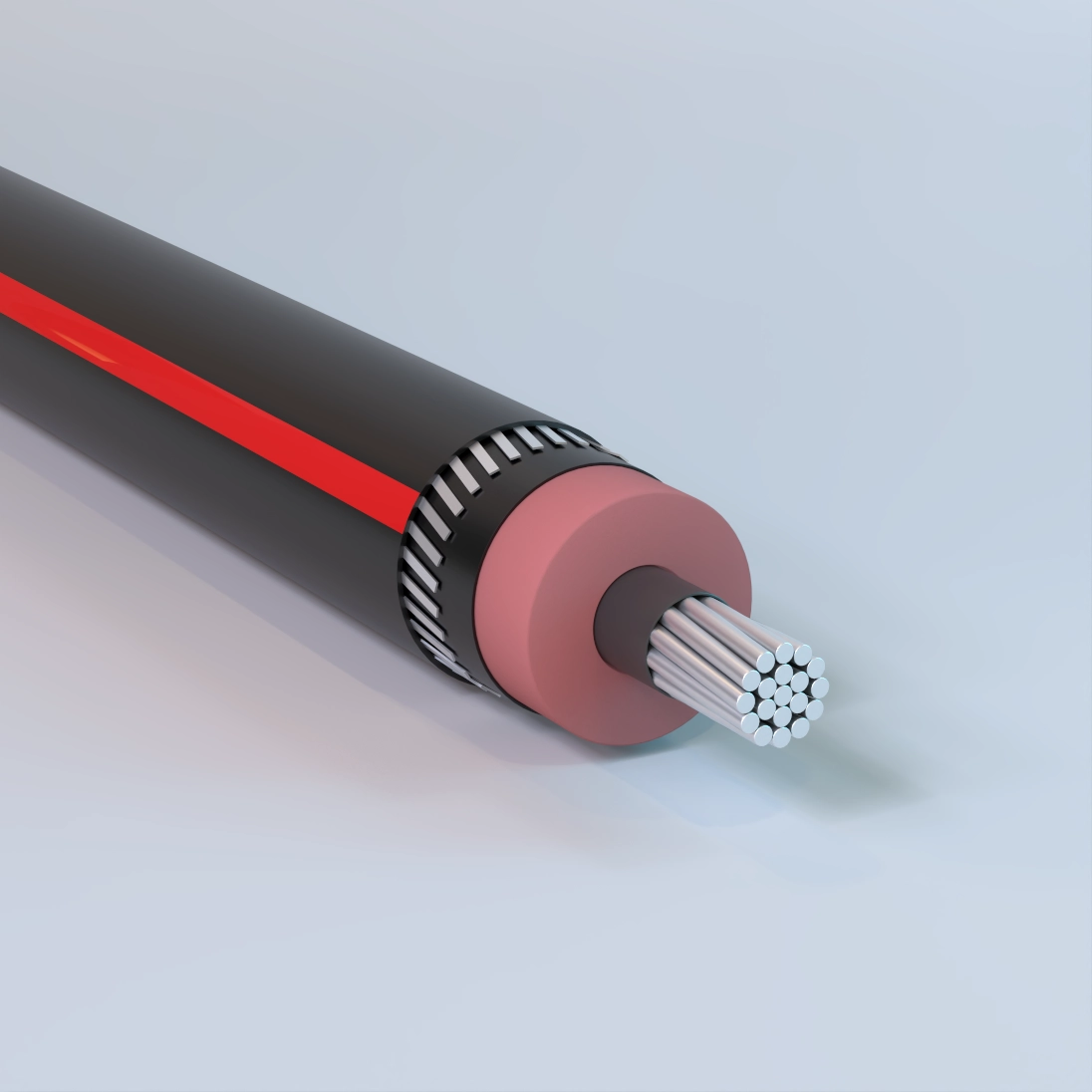
Primary UD
Underground, EPR Insulation, LLDPE Jacket, Tinned Copper Flat Strap Neutral, 15kV – Aluminum
Used for underground primary residential and commercial distribution circuits. May be used in wet or dry locations, installed in underground ducts or direct burial.
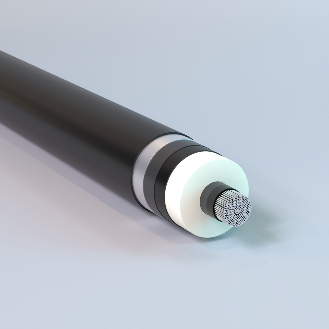
High Voltage, Smooth Aluminum Shield/Sheath
XLPE Insulation, HDPE Jacket, 69kV-138kV – Aluminum
Used for transmission and distribution circuits in cities with high load densities. Also, for industrial and commercial installations. May be installed in wet or dry locations indoors or outdoors in conduit and underground ducts.
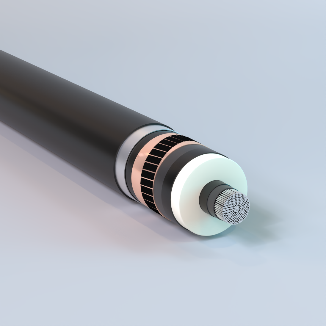
High Voltage, Wire and Tape Shield
XLPE Insulation, HDPE Jacket, 69kV-138kV – Aluminum
Used for transmission and distribution circuits in cities with high load densities. Also, for industrial and commercial installations. May be installed in wet or dry locations indoors or outdoors in conduit and underground ducts.
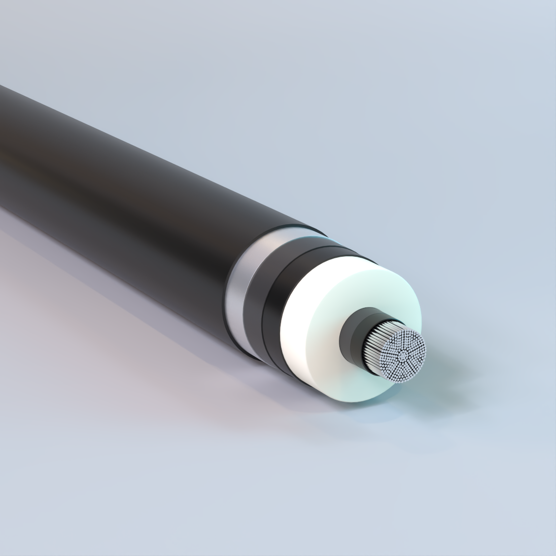
Extra High Voltage, Smooth Aluminum Shield/Sheath
XLPE Insulation, HDPE Jacket, 230kV – Aluminum
Used for transmission systems in urban and industrial installations with high load density. May be installed in wet or dry locations indoors or outdoors in conduit and underground ducts.

Secondary URD AA-8000, Tri-Rated, Mobile Home Feeder
Underground, Compact Conductor, XLPE Insulation, 600V – Aluminum
Designed to connect mobile homes to an electrical supply where permanent wiring is required. Can also be used for general purpose wiring in circuits not exceeding 600 volts. May be used in wet or dry locations, installed in conduit, duct, and directly buried in earth not exceeeding 90°C in accordance with requirements of the NEC®.
Copper Conductor

Bare Copper Conductor Solid
Hard, Medium-Hard, or Soft-Drawn
Used for grounding purposes in accordance with the National Electrical Code (NEC). Soft-drawn solid or stranded conductors are used for grounding connections in circuits, machinery, equipment, and counterpoise grounding systems. Hard-drawn conductors are suitable for overhead transmission and distribution lines and specified grounding applications. Also available tinned.
Physical Data
| Bare Copper Conductors Solid | |||||||||
|---|---|---|---|---|---|---|---|---|---|
| Breaking Strength | |||||||||
| Size | Area | Wire OD | Net Weight |
Hard Drawn Rated Strength |
dc Resistance @ 20 °C |
Medium-Hard Drawn Rated Strength |
dc Resistance @ 20 °C |
Soft Drawn (Annealed) Rated Strength |
dc Resistance @ 20 °C |
| AWG | cmil | in | lb/kft | lb | Ω/kft | lb | Ω/kft | lb | Ω/kft |
| 14 | 4110 | 0.0641 | 12 | 214 | 2.626 | 167 | 2.613 | 124 | 2.525 |
| 12 | 6530 | 0.0808 | 20 | 337 | 1.652 | 261 | 1.643 | 198 | 1.588 |
| 10 | 10380 | 0.1019 | 31 | 529 | 1.039 | 410 | 1.033 | 314 | 0.999 |
| 8 | 16510 | 0.1285 | 50 | 826 | 0.653 | 644 | 0.65 | 480 | 0.628 |
| 6 | 26240 | 0.162 | 79 | 1280 | 0.411 | 1010 | 0.409 | 763 | 0.395 |
| 4 | 41740 | 0.2043 | 126 | 1970 | 0.258 | 1584 | 0.257 | 1213 | 0.249 |
| 3 | 52620 | 0.2294 | 159 | 2439 | 0.205 | 1984 | 0.204 | 1530 | 0.197 |
| 2 | 66360 | 0.2576 | 201 | 3003 | 0.163 | 2450 | 0.162 | 1929 | 0.156 |
| The above data are approximate and subject to normal manufacturing tolerances. Where required, the compatibility with glands, connectors and accessories should be verified using actual dimensions of the product. Other sizes available upon request. | |||||||||
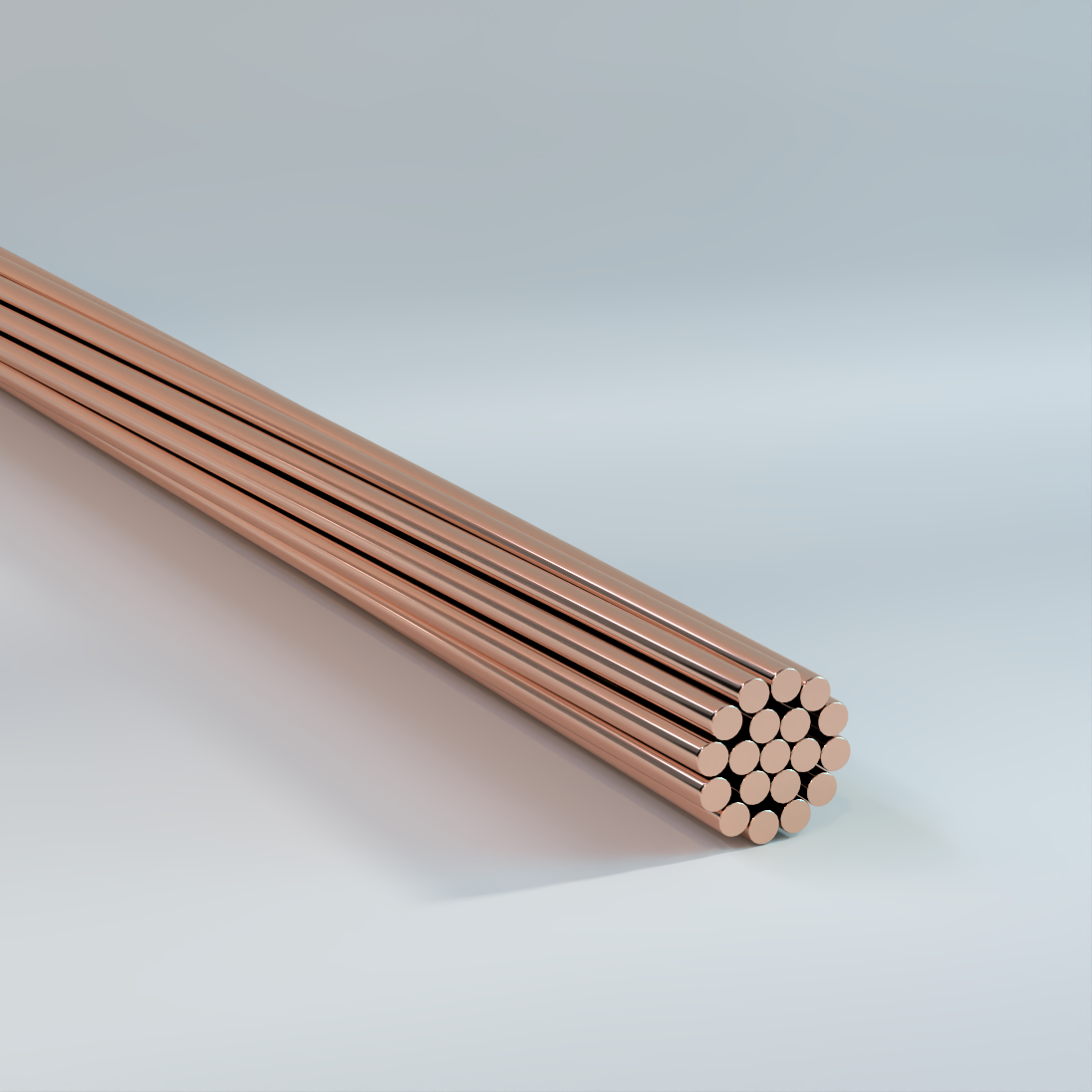
Bare Copper Conductor Stranded
Hard, Medium-Hard, or Soft-Drawn
Used for grounding purposes in accordance with the National Electrical Code (NEC). Soft-drawn solid or stranded conductors are used for grounding connections in circuits, machinery, equipment, and counterpoise grounding systems. Hard-drawn conductors are suitable for overhead transmission and distribution lines and specified grounding applications. Also available tinned.
Physical Data
| Bare Copper Conductors Stranded | ||||||||
|---|---|---|---|---|---|---|---|---|
| Size | Area | Class A | Class B | Net Weight | dc Resistance* | |||
| AWG | kcmil | cmil | Number of | OD | Number of | OD | lb/kft | |
| Strands | in | Strands | in | 20 °C | ||||
| 14 | — | 4110 | — | — | 7 | 0.0726 | 13 | 2.58 |
| 12 | — | 6530 | — | — | 7 | 0.0915 | 20 | 1.63 |
| 10 | — | 10380 | — | — | 7 | 0.116 | 32 | 1.02 |
| 8 | — | 16510 | — | — | 7 | 0.146 | 51 | 0.64 |
| 6 | — | 26240 | — | — | 7 | 0.184 | 81 | 0.403 |
| 4 | — | 41740 | 7 | 0.232 | 7 | 0.232 | 129 | 0.253 |
| 3 | — | 52620 | 7 | 0.26 | 7 | 0.26 | 163 | 0.201 |
| 2 | — | 66360 | 7 | 0.292 | 7 | 0.292 | 205 | 0.159 |
| 1 | — | 83690 | 7 | 0.328 | 19 | 0.332 | 258 | 0.127 |
| 1/0 | — | 105600 | 7 | 0.368 | 19 | 0.373 | 326 | 0.1 |
| 2/0 | — | 133100 | 7 | 0.414 | 19 | 0.419 | 411 | 0.795 |
| 3/0 | — | 167800 | 7 | 0.464 | 19 | 0.47 | 518 | 0.063 |
| 4/0 | — | 211600 | 7 | 0.522 | 19 | 0.528 | 653 | 0.05 |
| — | 250 | 250000 | 19 | 0.574 | 37 | 0.575 | 772 | 0.0423 |
| — | 300 | 300000 | 19 | 0.629 | 37 | 0.63 | 926 | 0.0353 |
| — | 350 | 350000 | 19 | 0.679 | 37 | 0.681 | 1081 | 0.0302 |
| — | 400 | 400000 | 19 | 0.726 | 37 | 0.728 | 1235 | 0.0264 |
| — | 450 | 450000 | 37 | 0.772 | 37 | 0.772 | 1389 | 0.0235 |
| — | 500 | 500000 | 37 | 0.813 | 37 | 0.813 | 1544 | 0.0192 |
| — | 600 | 600000 | 37 | 0.891 | 61 | 0.893 | 1883 | 0.0177 |
| — | 750 | 750000 | 61 | 0.998 | 61 | 0.998 | 2316 | 0.0141 |
| — | 1000 | 100000 | 61 | 1.152 | 61 | 1.152 | 3088 | 0.0106 |
| — | 1250 | 125000 | 61 | 1.288 | 91 | 1.289 | 3859 | 0.0085 |
| — | 1500 | 150000 | 61 | 1.411 | 91 | 1.412 | 4631 | 0.0071 |
| — | 1750 | 175000 | 91 | 1.526 | 127 | 1.526 | 5403 | 0.006 |
| — | 2000 | 200000 | 91 | 1.63 | 127 | 1.632 | 6175 | 0.0053 |
| The above data are approximate and subject to normal manufacturing tolerances. Where required, the compatibility with glands, connectors and accessories should be verified using actual dimensions of the product. Other sizes available upon request. *Direct current resistances apply to Class B, C, and D stranding. | ||||||||
| Bare Copper Conductors Stranded (cont.) | |||||||||
|---|---|---|---|---|---|---|---|---|---|
| Breaking Strength | |||||||||
| Size | Strands | Hard Drawn Rated Strength |
dc Resistance @ 20 °C |
Medium-Hard Drawn Rated Strength |
dc Resistance @ 20 °C |
Soft Drawn (Annealed) Rated Strength |
dc Resistance @ 20 °C |
Allowable Ampacity † |
|
| AWG | kcmil | lb | Ω/kft | lb | Ω/kft | lb | Ω/kft | ||
| 14 | — | 7 | 197 | 2.679 | 158 | 2.665 | — | — | — |
| 12 | — | 7 | 311 | 1.685 | 248 | 1.676 | — | — | — |
| 10 | — | 7 | 492 | 1.06 | 389 | 1.054 | — | — | — |
| 8 | — | 7 | 777 | 0.6663 | 610 | 0.6629 | 499 | 0.6408 | 98 |
| 6 | — | 7 | 1228 | 0.4191 | 959 | 0.4169 | 794 | 0.403 | 124 |
| 4 | — | 7 | 1938 | 0.2636 | 1505 | 0.2622 | 1320 | 0.2534 | 155 |
| 3 | — | 7 | 2433 | 0.209 | 1885 | 0.2079 | 1670 | 0.201 | — |
| 2 | — | 7 | 3050 | 0.166 | 2360 | 0.165 | 2110 | 0.1578 | 209 |
| 1 | — | 7 | 3801 | 0.1316 | 2955 | 0.1309 | 2552 | 0.1252 | — |
| 1/0 | — | 7 | 4752 | 0.1042 | 3705 | 0.1037 | 3221 | 0.1002 | 282 |
| 2/0 | — | 7 | 5926 | 0.08267 | 4640 | 0.08224 | 4062 | 0.07949 | 329 |
| 3/0 | — | 7 | 7366 | 0.06556 | 5812 | 0.06522 | 5118 | 0.06304 | 382 |
| 4/0 | — | 7 | 9154 | 0.05199 | 7278 | 0.05172 | 6459 | 0.04999 | 444 |
| 4/0 | — | 19 | 9617 | 0.05199 | 7479 | 0.05172 | 6453 | 0.04999 | 444 |
| — | 250 | 19 | 11360 | 0.044 | 8836 | 0.04378 | 7627 | 0.04231 | 494 |
| — | 250 | 37 | 11600 | 0.044 | 8952 | 0.04378 | 7940 | 0.04231 | 494 |
| — | 300 | 19 | 13510 | 0.03667 | 10530 | 0.03648 | 9160 | 0.03526 | 556 |
| — | 350 | 19 | 15590 | 0.03143 | 12200 | 0.03127 | 10680 | 0.03022 | — |
| — | 500 | 37 | 22510 | 0.022 | 17550 | 0.02189 | 15240 | 0.02116 | 773 |
| — | 600 | 37 | 27020 | 0.01834 | 21060 | 0.01825 | 18300 | 0.01763 | — |
| — | 750 | 61 | 34090 | 0.01467 | 26510 | 0.01459 | 22890 | 0.0141 | 1000 |
| — | 1000 | 61 | 45030 | 0.011 | 35100 | 0.01094 | 30500 | 0.01058 | 1193 |
| † Ampacity per NEC table 310.15 (B) (21) based on 80°C Conductor Temperature, 40°C Ambient Temperature, 2ft/s Wind in Sun. | |||||||||
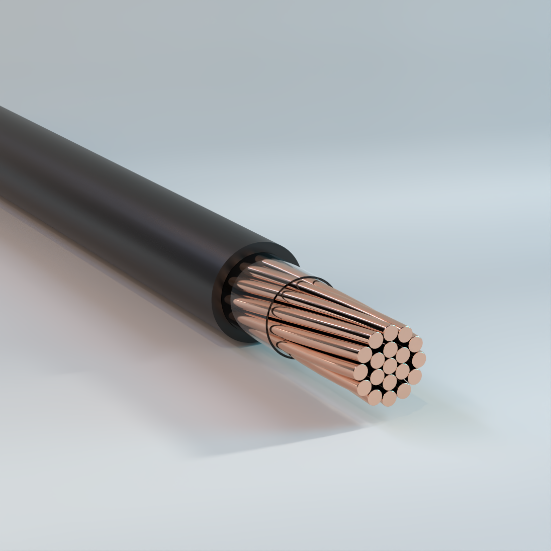
Covered Line Wire
Overhead, XLPE or PE Insulation, Single – Copper
Used for the distribution of electrical energy under normal condition of overhead (aerial) installation and service outdoors. Approved for use on insulators for overhead circuits. Otherwise treated as a bare conductor.
Physical Data
| Covered Line Wire XLPE or PE Insulation, Single | |||||||
|---|---|---|---|---|---|---|---|
| Size AWG or kcmil | Number of Strands |
Covering Thickness |
Cable OD |
Weight | dc Resistance | ||
| mil | in | PE | XLPE | Hard-drawn | Soft | ||
| lb/kft | lb/kft | 25 °C | 25 °C | ||||
| 6 | 1 | 30 | 0.23 | 87 | 87 | 0.419 | 0.403 |
| 4 | 1 | 30 | 0.27 | 136 | 136 | 0.264 | 0.253 |
| 2 | 1 | 45 | 0.35 | 220 | 219 | 0.166 | 0.159 |
| 6 | 7 | 30 | 0.24 | 91 | 91 | 0.428 | 0.411 |
| 4 | 7 | 30 | 0.29 | 142 | 142 | 0.269 | 0.258 |
| 2 | 7 | 45 | 0.38 | 229 | 229 | 0.169 | 0.162 |
| 1/0 | 7 | 60 | 0.49 | 367 | 367 | 0.106 | 0.102 |
| 2/0 | 19 | 60 | 0.53 | 455 | 454 | 0.084 | 0.081 |
| 3/0 | 19 | 60 | 0.58 | 567 | 567 | 0.067 | 0.0642 |
| 4/0 | 19 | 60 | 0.64 | 709 | 709 | 0.053 | 0.051 |
| 250 | 19 | 60 | 0.68 | 833 | 833 | 0.045 | 0.0431 |
| 300 | 19 | 60 | 0.74 | 993 | 993 | 0.037 | 0.036 |
| 350 | 19 | 60 | 0.79 | 1155 | 1154 | 0.032 | 0.0308 |
| 500 | 37 | 80 | 0.96 | 1650 | 1647 | 0.022 | 0.0216 |
| 750 | 61 | 80 | 1.14 | 2440 | 2437 | 0.015 | 0.0144 |
| 1000 | 61 | 95 | 1.32 | 3258 | 3257 | 0.011 | 0.0108 |
| The above data are approximate and subject to normal manufacturing tolerances. Where required, the compatibility with glands, connectors and accessories should be verified using actual dimensions of the product. Other sizes available upon request. | |||||||
Ampacity Data
| Covered Line Wire | |
|---|---|
| Conductor Size AWG/kcmil |
Ampacity |
| 8 | 103 |
| 6 | 130 |
| 4 | 163 |
| 2 | 219 |
| 1/0 | 297 |
| 2/0 | 344 |
| 3/0 | 401 |
| 4/0 | 466 |
| 250 | 519 |
| 300 | 584 |
| 500 | 812 |
| 750 | 1050 |
| 1000 | 1253 |
| NEC Table 310.15(B)(21) (formerly Table 310.21) Ampacities of Bare or Covered Conductors in Free Air, Based on 40 °C (104 °F) Ambient, 80 °C (176 °F) Total Conductor Temperature, 610 mm/s (2 ft/s) Wind Velocity. | |
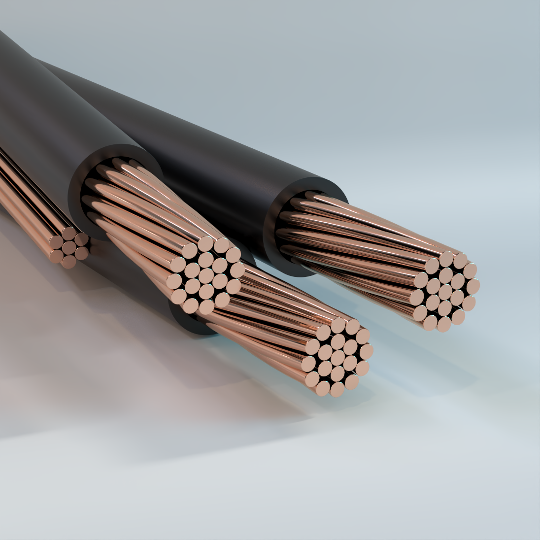
Service Drop
Overhead, Duplex/Triplex/Quadruplex, XLPE or PE Insulation, 600V – Copper
Used for overhead distribution of electrical energy, such as a supply power, from pole-mounted transformer to the user’s service head where connection to the service entrance cable is made. Also, for temporary services and street light installations.
Physical Data
| Duplex | ||||||||
|---|---|---|---|---|---|---|---|---|
| Code Word | Copper Phase Conductor | HD CU, Neutral Messenger | Weight | |||||
| Size | Number of Strands | Insulation Thickness |
Size | Number of Strands | Rated Strength | PE | XLPE | |
| AWG or kcmil | mil | AWG or kcmil | lb | lb/kft | lb/kft | |||
| Copper Conductor & Neutral Messenger | ||||||||
| Theta | 8 | 7 | 45 | 10 | 1 | 529 | 97 | 96 |
| Iota | 8 | 7 | 45 | 8 | 1 | 826 | 116 | 115 |
| Kappa | 8 | 7 | 45 | 8 | 7 | 777 | 117 | 116 |
| Omega | 8 | 1 | 45 | 8 | 1 | 826 | 113 | 112 |
| Lambda | 6 | 7 | 45 | 8 | 1 | 826 | 149 | 149 |
| Omicron | 6 | 7 | 45 | 6 | 1 | 1280 | 179 | 179 |
| Sigma | 6 | 7 | 45 | 6 | 7 | 1228 | 181 | 180 |
| (No Code) | 4 | 7 | 45 | 4 | 1 | 1970 | 279 | 279 |
| (No Code) | 4 | 7 | 45 | 4 | 7 | 1938 | 282 | 282 |
| (No Code) | 2 | 7 | 45 | 2 | 7 | 3050 | 442 | 441 |
| (No Code) | 1/0 | 19 | 60 | 1/0 | 7 | 4752 | 703 | 702 |
| The above data are approximate and subject to normal manufacturing tolerances. Where required, the compatibility with glands, connectors and accessories should be verified using actual dimensions of the product. Other sizes available upon request. | ||||||||
| Triplex | ||||||||
|---|---|---|---|---|---|---|---|---|
| Code Word |
Copper Phase Conductor | HD CU, Neutral Messenger | Weight | |||||
| Size | Number of Strands |
Insulation Thickness |
Size | Number of Strands |
Rated Strength |
PE | XLPE | |
| AWG or kcmil |
mil | AWG or kcmil |
lb | lb/kft | lb/kft | |||
| Copper Conductor & Neutral Messenger | ||||||||
| Pica | 8 | 7 | 45 | 10 | 1 | 529 | 149 | 160 |
| Bodoni | 8 | 7 | 45 | 8 | 1 | 826 | 167 | 179 |
| Garamond | 8 | 7 | 45 | 8 | 7 | 777 | 169 | 180 |
| Columbian | 8 | 1 | 45 | 8 | 1 | 826 | 164 | 174 |
| Tudor | 6 | 7 | 45 | 8 | 1 | 826 | 232 | 246 |
| Futura | 6 | 7 | 45 | 6 | 1 | 1280 | 262 | 276 |
| Gothic | 6 | 7 | 45 | 6 | 7 | 1228 | 263 | 278 |
| Nonpareil | 4 | 7 | 45 | 6 | 1 | 1280 | 363 | 381 |
| Ionic | 4 | 7 | 45 | 4 | 1 | 1970 | 411 | 429 |
| Caslon | 4 | 7 | 45 | 4 | 7 | 1938 | 413 | 432 |
| Minion | 2 | 7 | 45 | 4 | 1 | 1970 | 571 | 594 |
| Primer | 2 | 7 | 45 | 4 | 7 | 1938 | 574 | 596 |
| Century | 2 | 7 | 45 | 2 | 7 | 3050 | 651 | 674 |
| Corinthian | 1/0 | 19 | 60 | 1/0 | 7 | 4752 | 1036 | 1073 |
| (No Code) | 2/0 | 19 | 60 | 1/0 | 7 | 4752 | 1214 | 1255 |
| Doric | 2/0 | 19 | 60 | 2/0 | 7 | 5926 | 1301 | 1342 |
| (No Code) | 3/0 | 19 | 60 | 1/0 | 7 | 4752 | 1438 | 1485 |
| Tuscan | 3/0 | 19 | 60 | 3/0 | 7 | 7366 | 1634 | 1681 |
| Composite | 4/0 | 19 | 60 | 4/0 | 7 | 9154 | 2054 | 2107 |
| The above data are approximate and subject to normal manufacturing tolerances. Where required, the compatibility with glands, connectors and accessories should be verified using actual dimensions of the product. Other sizes available upon request. | ||||||||
| Quadruplex | ||||||||
|---|---|---|---|---|---|---|---|---|
| Code Word |
Copper Phase Conductor | HD CU, Neutral Messenger | Weight | |||||
| Size | Number of Strands |
Insulation Thickness |
Size | Number of Strands |
Rated Strength |
PE | XLPE | |
| AWG or kcmil |
mil | AWG or kcmil |
lb | lb/kft | lb/kft | |||
| Copper Conductor & Neutral Messenger | ||||||||
| Atlanta | 6 | 7 | 45 | 6 | 1 | 1280 | 344 | 359 |
| Tallahassee | 6 | 7 | 45 | 6 | 7 | 1228 | 346 | 361 |
| Baton Rouge | 4 | 7 | 45 | 4 | 1 | 1970 | 542 | 560 |
| Richmond | 4 | 7 | 45 | 4 | 7 | 1938 | 545 | 563 |
| (No Code) | 2 | 7 | 45 | 4 | 7 | 1938 | 782 | 805 |
| Jackson | 2 | 7 | 45 | 2 | 1 | 3003 | 856 | 879 |
| Seatle | 2 | 7 | 45 | 2 | 7 | 3050 | 860 | 883 |
| (No Code) | 1/0 | 19 | 60 | 2 | 7 | 3050 | 1245 | 1282 |
| Nashville | 1/0 | 19 | 60 | 1/0 | 7 | 4752 | 1368 | 1405 |
| Lincoln | 2/0 | 19 | 60 | 2/0 | 7 | 5926 | 1720 | 1761 |
| Raleigh | 3/0 | 19 | 60 | 3/0 | 7 | 7366 | 2163 | 2209 |
| Denver | 4/0 | 19 | 60 | 4/0 | 7 | 9154 | 2721 | 2773 |
| The above data are approximate and subject to normal manufacturing tolerances. Where required, the compatibility with glands, connectors and accessories should be verified using actual dimensions of the product. Other sizes available upon request. | ||||||||
Ampacity Data
| Cable Construction 2PLX, 3PLX, & 4PLX | ||
|---|---|---|
| Conductor Size AWG/kcmil |
Ampacity | |
| 75 °C (167 °F) | 90 °C (194 °F) | |
| 14 | 20 | 25 |
| 12 | 25 | 30 |
| 10 | 35 | 40 |
| 8 | 50 | 55 |
| 6 | 65 | 75 |
| 4 | 85 | 95 |
| 3 | 100 | 115 |
| 2 | 115 | 130 |
| 1 | 130 | 145 |
| 1/0 | 150 | 170 |
| 2/0 | 175 | 195 |
| 3/0 | 200 | 225 |
| 4/0 | 230 | 260 |
| 250 | 255 | 290 |
| 300 | 285 | 320 |
| 350 | 310 | 350 |
| 400 | 335 | 380 |
| 500 | 380 | 430 |
| 600 | 420 | 475 |
| 700 | 460 | 520 |
| 750 | 475 | 535 |
| 800 | 490 | 555 |
| 900 | 520 | 585 |
| 1000 | 545 | 615 |
| 1250 | 590 | 665 |
| 1500 | 625 | 705 |
| 1750 | 650 | 735 |
| 2000 | 665 | 750 |
| NEC Table 310.15(B)(16) (formerly Table 310.16) Allowable Ampacities of Insulated Conductors .Rated Up to and Including 2000 Volts, 60 °C Through 90 °C (140 °F Through 194 °F), Not More Than Three Current-Carrying Conductors in Raceway, Cable, or Earth (Directly Buried), Based on Ambient Temperature of 30 °C (86 °F)* | ||
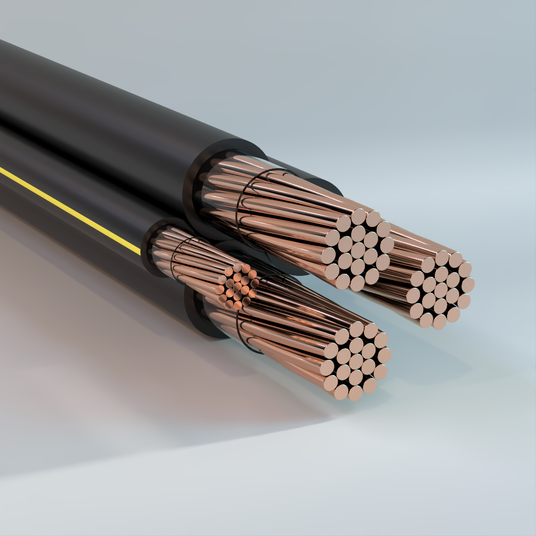
Secondary URD
Underground, Duplex/Triplex/Quadruplex, XLPE Insulation, 600V – Copper
Used for secondary distribution and underground service at 600 volts or less. May be used in ducts or direct burial.
Physical Data
| Single | ||||||
|---|---|---|---|---|---|---|
| Code Word |
Phase Conductor | XLPE Insulation | ||||
| Size AWG or kcmil |
Number of Strands |
Insulation Thickness mil |
Cable OD mil |
Code Word Suffix |
Net Weight lb/kft |
|
| Princeton | 6 | 7 | 60 | 0.31 | /XLP | 45 |
| Mercer | 4 | 7 | 60 | 0.35 | /XLP | 65 |
| Clemson | 2 | 7 | 60 | 0.41 | /XLP | 94 |
| Kenyon | 1 | 19 | 80 | 0.49 | /XLP | 125 |
| Harvard | 1/0 | 19 | 80 | 0.53 | /XLP | 150 |
| Yale | 2/0 | 19 | 80 | 0.57 | /XLP | 182 |
| Tufts | 3/0 | 19 | 80 | 0.62 | /XLP | 221 |
| Beloit | 4/0 | 19 | 80 | 0.68 | /XLP | 271 |
| Hofstra | 250 | 37 | 95 | 0.76 | /XLP | 323 |
| Gonzaga | 300 | 37 | 95 | 0.81 | /XLP | 377 |
| Rutgers | 350 | 37 | 95 | 0.86 | /XLP | 431 |
| Dartmouth | 400 | 37 | 95 | 0.91 | /XLP | 485 |
| Brown | 450 | 37 | 95 | 0.95 | /XLP | 539 |
| Emory | 500 | 37 | 95 | 0.99 | /XLP | 592 |
| Duke | 600 | 61 | 110 | 1.10 | /XLP | 711 |
| Furman | 700 | 61 | 110 | 1.17 | /XLP | 816 |
| Sewanee | 750 | 61 | 110 | 1.20 | /XLP | 870 |
| Fordham | 1000 | 61 | 110 | 1.35 | /XLP | 1129 |
| The above data are approximate and subject to normal manufacturing tolerances. Other sizes available upon request. | ||||||
| Duplex | ||||||||||
|---|---|---|---|---|---|---|---|---|---|---|
| Code Word |
Phase Conductor | Neutral Conductor | Cable OD | XLPE Insulation | ||||||
| Size AWG or kcmil |
Number of Strands |
Insulation Thickness mils |
Size AWG or kcmil |
Number of Strands |
Insulation Thickness mil |
Single Phase in |
Complete Cable in |
Code Word Suffix |
Net Weight | |
| lb/kft | ||||||||||
| Alcorn | 8 | 1 | 60 | 8 | 1 | 60 | 0.25 | 0.50 | /XLP/EYS | 62.2 |
| Claflin | 6 | 7 | 60 | 6 | 7 | 60 | 0.31 | 0.61 | /XLP/EYS | 92.8 |
| Delgado | 4 | 7 | 60 | 4 | 7 | 60 | 0.35 | 0.70 | /XLP/EYS | 131.7 |
| Cedarcrest | 2 | 7 | 60 | 4 | 7 | 60 | 0.41 | 0.82 | /XLP/EYS | 161.4 |
| Everett | 2 | 7 | 60 | 2 | 7 | 60 | 0.41 | 0.82 | /XLP/EYS | 191.2 |
| Findlay | 2/0 | 19 | 80 | 2/0 | 19 | 80 | 0.57 | 1.15 | /XLP/EYS | 372.0 |
| Hanover | 4/0 | 19 | 80 | 4/0 | 19 | 80 | 0.68 | 1.36 | /XLP/EYS | 552.1 |
| Glenville | 350 | 37 | 95 | 350 | 37 | 95 | 0.86 | 1.72 | /XLP/EYS | 880.2 |
| The above data are approximate and subject to normal manufacturing tolerances. Other sizes available upon request. | ||||||||||
| Triplex | ||||||||||
|---|---|---|---|---|---|---|---|---|---|---|
| Code Word |
Phase Conductor | Neutral Conductor | Cable OD | XLPE Insulation | ||||||
| Size AWG or kcmil |
Number of Strands |
Insulation Thickness mils |
Size AWG or kcmil |
Number of Strands |
Insulation Thickness mil |
Single Phase in |
Complete Cable in |
Code Word Suffix |
Net Weight | |
| lb/kft | ||||||||||
| Erskine | 6 | 7 | 60 | 6 | 7 | 60 | 0.31 | 0.66 | /XLP/EYS | 139 |
| Vassar | 4 | 7 | 60 | 4 | 7 | 60 | 0.35 | 0.76 | /XLP/EYS | 198 |
| Stephens | 2 | 7 | 60 | 4 | 7 | 60 | 0.41 | 0.88 | /XLP/EYS | 257 |
| Ramapo | 2 | 7 | 60 | 2 | 7 | 60 | 0.41 | 0.88 | /XLP/EYS | 287 |
| Grossmont | 1 | 19 | 80 | 1 | 19 | 80 | 0.49 | 1.06 | /XLP/EYS | 383 |
| Brenau | 1/0 | 19 | 80 | 2 | 7 | 60 | 0.53 | 1.14 | /XLP/EYS | 402 |
| Bergen | 1/0 | 19 | 80 | 1/0 | 19 | 80 | 0.53 | 1.14 | /XLP/EYS | 460 |
| Fisk | 2/0 | 19 | 80 | 2 | 7 | 60 | 0.57 | 1.24 | /XLP/EYS | 468 |
| Converse | 2/0 | 19 | 80 | 1 | 19 | 80 | 0.57 | 1.24 | /XLP/EYS | 500 |
| Shaw | 2/0 | 19 | 80 | 1/0 | 19 | 80 | 0.57 | 1.24 | /XLP/EYS | 525 |
| Hunter | 2/0 | 19 | 80 | 2/0 | 19 | 80 | 0.57 | 1.24 | /XLP/EYS | 558 |
| Calvert | 3/0 | 19 | 80 | 2 | 7 | 60 | 0.62 | 1.34 | /XLP/EYS | 547 |
| Chase | 3/0 | 19 | 80 | 1 | 19 | 80 | 0.62 | 1.34 | /XLP/EYS | 579 |
| Hollins | 3/0 | 19 | 80 | 1/0 | 19 | 80 | 0.62 | 1.34 | /XLP/EYS | 605 |
| Rockland | 3/0 | 19 | 80 | 3/0 | 19 | 80 | 0.62 | 1.34 | /XLP/EYS | 677 |
| Coburn | 4/0 | 19 | 80 | 1 | 19 | 80 | 0.68 | 1.47 | /XLP/EYS | 680 |
| Molloy | 4/0 | 19 | 80 | 1/0 | 19 | 80 | 0.68 | 1.47 | /XLP/EYS | 705 |
| Sweetbriar | 4/0 | 19 | 80 | 2/0 | 19 | 80 | 0.68 | 1.47 | /XLP/EYS | 738 |
| Monmouth | 4/0 | 19 | 80 | 4/0 | 19 | 80 | 0.68 | 1.47 | /XLP/EYS | 828 |
| Aquinas | 250 | 37 | 95 | 2/0 | 19 | 80 | 0.76 | 1.63 | /XLP/EYS | 844 |
| Pratt | 250 | 37 | 95 | 3/0 | 19 | 80 | 0.76 | 1.63 | /XLP/EYS | 884 |
| Yeshiva | 250 | 37 | 95 | 250 | 37 | 95 | 0.76 | 1.63 | /XLP/EYS | 987 |
| Allen | 300 | 37 | 95 | 2/0 | 19 | 80 | 0.81 | 1.75 | /XLP/EYS | 956 |
| Greenville | 350 | 37 | 95 | 1/0 | 19 | 80 | 0.86 | 1.85 | /XLP/EYS | 1034 |
| Gloucester | 350 | 37 | 95 | 3/0 | 19 | 80 | 0.86 | 1.85 | /XLP/EYS | 1106 |
| Wesleyan | 350 | 37 | 95 | 4/0 | 19 | 80 | 0.86 | 1.85 | /XLP/EYS | 1156 |
| Newark | 350 | 37 | 95 | 350 | 37 | 95 | 0.86 | 1.85 | /XLP/EYS | 1320 |
| Old Dominion | 500 | 37 | 95 | 4/0 | 19 | 80 | 0.99 | 2.13 | /XLP/EYS | 1483 |
| Holyoke | 500 | 37 | 95 | 300 | 37 | 95 | 0.99 | 2.13 | /XLP/EYS | 1592 |
| Rider | 500 | 37 | 95 | 350 | 37 | 95 | 0.99 | 2.13 | /XLP/EYS | 1647 |
| Westchester | 500 | 37 | 95 | 500 | 37 | 95 | 0.99 | 2.13 | /XLP/EYS | 1811 |
| Villanova | 750 | 61 | 110 | 350 | 37 | 95 | 1.20 | 2.58 | /XLP/EYS | 2215 |
| Voorhees | 750 | 61 | 110 | 450 | 37 | 95 | 1.20 | 2.58 | /XLP/EYS | 2324 |
| Fairfield | 750 | 61 | 110 | 500 | 37 | 95 | 1.20 | 2.58 | /XLP/EYS | 2379 |
| Seton Hall | 750 | 61 | 110 | 750 | 61 | 110 | 1.20 | 2.58 | /XLP/EYS | 2662 |
| The above data are approximate and subject to normal manufacturing tolerances. Other sizes available upon request. | ||||||||||
Ampacity Data
| Cable Construction Single Insulated Conductor | ||
|---|---|---|
| Conductor Size AWG/kcmil |
Ampacity | |
| 75 °C (167 °F) | 90 °C (194 °F) | |
| 14 | 30 | 35 |
| 12 | 35 | 40 |
| 10 | 50 | 55 |
| 8 | 70 | 80 |
| 6 | 95 | 105 |
| 4 | 125 | 140 |
| 3 | 145 | 165 |
| 2 | 170 | 190 |
| 1 | 195 | 220 |
| 1/0 | 230 | 260 |
| 2/0 | 265 | 300 |
| 3/0 | 310 | 350 |
| 4/0 | 360 | 405 |
| 250 | 405 | 455 |
| 300 | 445 | 500 |
| 350 | 505 | 570 |
| 400 | 545 | 615 |
| 500 | 620 | 700 |
| 600 | 690 | 780 |
| 700 | 755 | 850 |
| 750 | 785 | 885 |
| 800 | 815 | 920 |
| 900 | 870 | 980 |
| 1000 | 935 | 1055 |
| 1250 | 1065 | 1200 |
| 1500 | 1175 | 1325 |
| 1750 | 1280 | 1445 |
| 2000 | 1385 | 1560 |
| NEC Table 310.15(B)(17) (formerly Table 310.17) Allowable Ampacities of Single Insulated Conductors Rated Up to and Including 2000 Volts in Free Air, Based on Ambient Temperature of 30 °C (86 °F)* | ||
| Cable Construction 2PLX, 3PLX, & 4PLX | ||
|---|---|---|
| Conductor Size AWG/kcmil |
Ampacity | |
| 75 °C (167 °F) | 90 °C (194 °F) | |
| 14 | 20 | 25 |
| 12 | 25 | 30 |
| 10 | 35 | 40 |
| 8 | 50 | 55 |
| 6 | 65 | 75 |
| 4 | 85 | 95 |
| 3 | 100 | 115 |
| 2 | 115 | 130 |
| 1 | 130 | 145 |
| 1/0 | 150 | 170 |
| 2/0 | 175 | 195 |
| 3/0 | 200 | 225 |
| 4/0 | 230 | 260 |
| 250 | 255 | 290 |
| 300 | 285 | 320 |
| 350 | 310 | 350 |
| 400 | 335 | 380 |
| 500 | 380 | 430 |
| 600 | 420 | 475 |
| 700 | 460 | 520 |
| 750 | 475 | 535 |
| 800 | 490 | 555 |
| 900 | 520 | 585 |
| 1000 | 545 | 615 |
| 1250 | 590 | 665 |
| 1500 | 625 | 705 |
| 1750 | 650 | 735 |
| 2000 | 665 | 750 |
| NEC Table 310.15(B)(16) (formerly Table 310.16) Allowable Ampacities of Insulated Conductors .Rated Up to and Including 2000 Volts, 60 °C Through 90 °C (140 °F Through 194 °F), Not More Than Three Current-Carrying Conductors in Raceway, Cable, or Earth (Directly Buried), Based on Ambient Temperature of 30 °C (86 °F)* | ||

Secondary URD Ruggedized
Underground, Duplex/Triplex/Quadruplex, XLPE Insulation, 600V – Copper
Used for secondary distribution and underground service at 600 volts or less. May be used in ducts or direct burial.
Physical Data
| Duplex XLPE Insulated, 600 V | ||||||||
|---|---|---|---|---|---|---|---|---|
| Phase Conductor | Neutral Conductor | Cable OD | Weight XLPE | |||||
| Size AWG or kcmil |
Number of Strands | Insulation Thickness |
Size AWG or kcmil |
Number of Strands | Insulation Thickness | Single Phase | Complete Cable | lb/kft |
| mil | mil | mil | in | |||||
| 8-7/w | 7 | 60 | 8 | 7 | 60 | 0.27 | 0.53 | 138 |
| 6-7/w | 7 | 60 | 6 | 7 | 60 | 0.3 | 0.6 | 207 |
| 4-7/w | 7 | 60 | 4 | 7 | 60 | 0.35 | 0.7 | 313 |
| The above data are approximate and subject to normal manufacturing tolerances. Other sizes available upon request. | ||||||||
| Triplex XLPE Insulated, 600 V | ||||||||
|---|---|---|---|---|---|---|---|---|
| Phase Conductor | Neutral Conductor | Cable OD | Weight XLPE | |||||
| Size AWG or kcmil |
Number of Strands |
Insulation Thickness |
Size AWG or kcmil |
Number of Strands |
Insulation Thickness |
Single Phase | Complete Cable | lb/kft |
| mil | mil | mil | in | |||||
| 6-7/w | 7 | 60 | 6 | 7 | 60 | 0.3 | 0.65 | 311 |
| 4-7/w | 7 | 60 | 4 | 7 | 60 | 0.35 | 0.75 | 470 |
| 2-7/w | 7 | 60 | 4 | 7 | 60 | 0.41 | 0.87 | 637 |
| 2-7/w | 7 | 60 | 2 | 7 | 60 | 0.41 | 0.87 | 721 |
| 1-19/w | 19 | 80 | 3 | 7 | 60 | 0.49 | 1.05 | 813 |
| 1/0-19/w | 19 | 80 | 2 | 7 | 60 | 0.53 | 1.13 | 1,007 |
| 1/0-19/w | 19 | 80 | 1/0 | 19 | 80 | 0.53 | 1.13 | 1,151 |
| 2/0-19/w | 19 | 80 | 1 | 19 | 80 | 0.57 | 1.23 | 1,262 |
| 2/0-19/w | 19 | 80 | 2/0 | 19 | 80 | 0.57 | 1.23 | 1,428 |
| 2/0-19/w | 19 | 80 | 2/0 | 19 | 80 | 0.57 | 1.23 | 1,428 |
| 2/0-19/w | 19 | 80 | 2/0 | 19 | 80 | 0.57 | 1.23 | 1,428 |
| 3/0-19/w | 19 | 80 | 1/0 | 19 | 80 | 0.62 | 1.34 | 1,568 |
| 3/0-19/w | 19 | 80 | 3/0 | 19 | 80 | 0.62 | 1.34 | 1,776 |
| 4/0-19/w | 19 | 80 | 2/0 | 19 | 80 | 0.68 | 1.46 | 2,199 |
| 4/0-19/w | 19 | 80 | 4/0 | 19 | 80 | 0.68 | 1.46 | 2,213 |
| 4/0-19/w | 19 | 80 | 4/0 | 19 | 80 | 0.68 | 1.46 | 2,213 |
| 250-37/w | 37 | 95 | 3/0 | 19 | 80 | 0.75 | 1.62 | 2,342 |
| 350-37/w | 37 | 95 | 4/0 | 19 | 80 | 0.85 | 1.84 | 3,148 |
| 350-37/w | 37 | 95 | 350 | 37 | 95 | 0.85 | 1.84 | 3,615 |
| 350-37/w | 37 | 95 | 350 | 37 | 95 | 0.85 | 1.84 | 3,615 |
| 500-37/w | 37 | 95 | 300 | 37 | 95 | 0.98 | 2.12 | 4,433 |
| 500-37/w | 37 | 95 | 350 | 37 | 95 | 0.98 | 2.12 | 4,598 |
| The above data are approximate and subject to normal manufacturing tolerances. Other sizes available upon request. | ||||||||
| Quadruplex XLPE Insulated, 600 V | ||||||||
|---|---|---|---|---|---|---|---|---|
| Phase Conductor | Neutral Conductor | Cable OD | Weight XLPE | |||||
| Size AWG or kcmil |
Number of Strands |
Insulation Thickness |
Size AWG or kcmil |
Number of Strands |
Insulation Thickness |
Single Phase | Complete Cable | lb/kft |
| mil | mil | mil | in | |||||
| 6-7/w | 7 | 60 | 6 | 7 | 60 | 0.3 | 0.73 | 414 |
| 4-7/w | 7 | 60 | 4 | 7 | 60 | 0.35 | 0.84 | 627 |
| 2-7/w | 7 | 60 | 4 | 7 | 60 | 0.35 | 0.98 | 877 |
| 2-7/w | 7 | 60 | 2 | 7 | 60 | 0.41 | 0.98 | 961 |
| 1-19/w | 19 | 80 | 3 | 7 | 60 | 0.38 | 1.17 | 1,123 |
| 1/0-19/w | 19 | 80 | 2 | 7 | 60 | 0.41 | 1.27 | 1,391 |
| 1/0-19/w | 19 | 80 | 1/0 | 19 | 80 | 0.53 | 1.27 | 1,534 |
| 2/0-19/w | 19 | 80 | 1 | 19 | 80 | 0.49 | 1.38 | 1,738 |
| 2/0-19/w | 19 | 80 | 2/0 | 19 | 80 | 0.57 | 1.38 | 1,905 |
| 3/0-19/w | 19 | 80 | 1/0 | 19 | 80 | 0.53 | 1.5 | 2,160 |
| 3/0-19/w | 19 | 80 | 3/0 | 19 | 80 | 0.62 | 1.5 | 2,369 |
| 4/0-19/w | 19 | 80 | 2/0 | 19 | 80 | 0.57 | 1.63 | 2,689 |
| 4/0-19/w | 19 | 80 | 4/0 | 19 | 80 | 0.68 | 1.63 | 2,951 |
| 250-37/w | 37 | 95 | 3/0 | 19 | 80 | 0.62 | 1.82 | 3,217 |
| 300-37/w | 37 | 95 | 4/0 | 19 | 80 | 0.68 | 1.95 | 3,857 |
| 350-37/w | 37 | 95 | 4/0 | 19 | 80 | 0.68 | 2.06 | 4,353 |
| 350-37/w | 37 | 95 | 350 | 37 | 95 | 0.85 | 2.06 | 4,821 |
| The above data are approximate and subject to normal manufacturing tolerances. Other sizes available upon request. | ||||||||
Ampacity Data
| Cable Construction Single Insulated Conductor | ||
|---|---|---|
| Conductor Size AWG/kcmil |
Ampacity | |
| 75 °C (167 °F) | 90 °C (194 °F) | |
| 14 | 30 | 35 |
| 12 | 35 | 40 |
| 10 | 50 | 55 |
| 8 | 70 | 80 |
| 6 | 95 | 105 |
| 4 | 125 | 140 |
| 3 | 145 | 165 |
| 2 | 170 | 190 |
| 1 | 195 | 220 |
| 1/0 | 230 | 260 |
| 2/0 | 265 | 300 |
| 3/0 | 310 | 350 |
| 4/0 | 360 | 405 |
| 250 | 405 | 455 |
| 300 | 445 | 500 |
| 350 | 505 | 570 |
| 400 | 545 | 615 |
| 500 | 620 | 700 |
| 600 | 690 | 780 |
| 700 | 755 | 850 |
| 750 | 785 | 885 |
| 800 | 815 | 920 |
| 900 | 870 | 980 |
| 1000 | 935 | 1055 |
| 1250 | 1065 | 1200 |
| 1500 | 1175 | 1325 |
| 1750 | 1280 | 1445 |
| 2000 | 1385 | 1560 |
| NEC Table 310.15(B)(17) (formerly Table 310.17) Allowable Ampacities of Single Insulated Conductors Rated Up to and Including 2000 Volts in Free Air, Based on Ambient Temperature of 30 °C (86 °F)* | ||
| Cable Construction 2PLX, 3PLX, & 4PLX | ||
|---|---|---|
| Conductor Size AWG/kcmil |
Ampacity | |
| 75 °C (167 °F) | 90 °C (194 °F) | |
| 14 | 20 | 25 |
| 12 | 25 | 30 |
| 10 | 35 | 40 |
| 8 | 50 | 55 |
| 6 | 65 | 75 |
| 4 | 85 | 95 |
| 3 | 100 | 115 |
| 2 | 115 | 130 |
| 1 | 130 | 145 |
| 1/0 | 150 | 170 |
| 2/0 | 175 | 195 |
| 3/0 | 200 | 225 |
| 4/0 | 230 | 260 |
| 250 | 255 | 290 |
| 300 | 285 | 320 |
| 350 | 310 | 350 |
| 400 | 335 | 380 |
| 500 | 380 | 430 |
| 600 | 420 | 475 |
| 700 | 460 | 520 |
| 750 | 475 | 535 |
| 800 | 490 | 555 |
| 900 | 520 | 585 |
| 1000 | 545 | 615 |
| 1250 | 590 | 665 |
| 1500 | 625 | 705 |
| 1750 | 650 | 735 |
| 2000 | 665 | 750 |
| NEC Table 310.15(B)(16) (formerly Table 310.16) Allowable Ampacities of Insulated Conductors .Rated Up to and Including 2000 Volts, 60 °C Through 90 °C (140 °F Through 194 °F), Not More Than Three Current-Carrying Conductors in Raceway, Cable, or Earth (Directly Buried), Based on Ambient Temperature of 30 °C (86 °F)* | ||
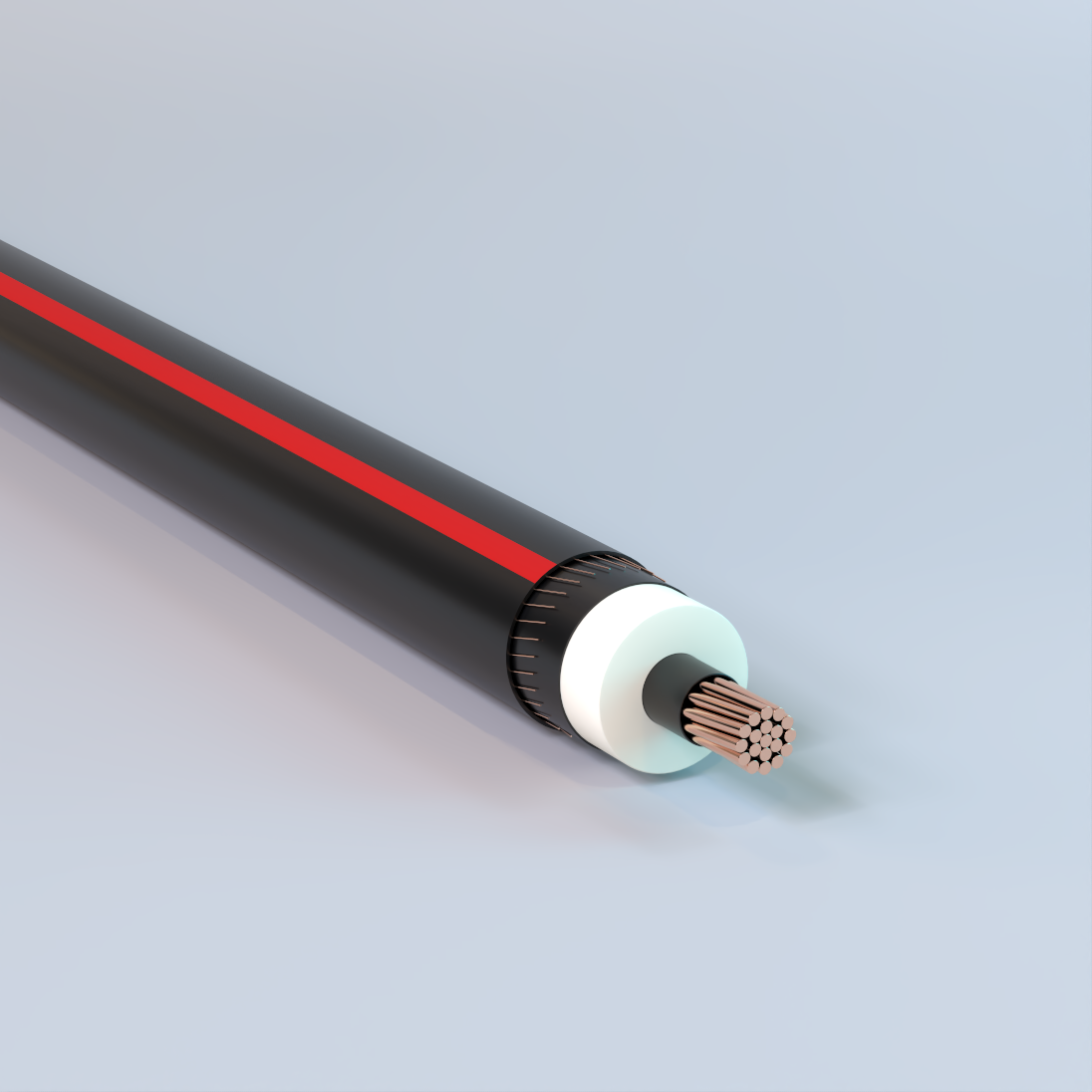
Primary-UD
Underground, TR-XLPE Insulation, LLDPE Jacket, Concentric Neutral, 5kV-35kV – Copper
Used for underground primary residential and commercial distribution circuits. May be used in wet or dry locations, installed in underground ducts or direct burial.
Physical Data
| 5 kV TR-XLPE Insulated | ||||||||||||
|---|---|---|---|---|---|---|---|---|---|---|---|---|
| Size AWG or kcmil |
Number of Strands |
Nominal OD Over Insulation |
1/3 Neutral | Full Neutral | ||||||||
| in | Number of Wires |
Size | Jacket Thickness |
Approximate Outside Diameter |
Approximate Net Weight |
Number of Wires |
Size | Jacket Thickness |
Approximate Outside Diameter |
Approximate Net Weight |
||
| AWG | mil | in | lb/kft | AWG | mil | in | lb/kft | |||||
| Copper 100% Insulation Level (90 mil) | ||||||||||||
| 2 | 7 | 0.5 | 6 | 14 | 50 | 0.81 | 469 | 16 | 14 | 50 | 0.81 | 589 |
| 1 | 19 | 0.54 | 7 | 14 | 50 | 0.84 | 547 | 13 | 12 | 50 | 0.88 | 730 |
| 1/0 | 19 | 0.58 | 9 | 14 | 50 | 0.88 | 653 | 16 | 12 | 50 | 0.92 | 870 |
| 2/0 | 19 | 0.63 | 11 | 14 | 50 | 0.93 | 779 | 13 | 10 | 50 | 1 | 1089 |
| 3/0 | 19 | 0.68 | 14 | 14 | 50 | 0.98 | 941 | 16 | 10 | 50 | 1.05 | 1309 |
| 4/0 | 19 | 0.73 | 18 | 14 | 50 | 1.03 | 1146 | 16 | 9 | 50 | 1.14 | 1613 |
| 250 | 37 | 0.79 | 13 | 12 | 50 | 1.12 | 1340 | — | — | — | — | — |
| 350 | 37 | 0.89 | 18 | 12 | 50 | 1.23 | 1785 | — | — | — | — | — |
| 500 | 37 | 1.02 | 17 | 10 | 50 | 1.42 | 2535 | — | — | — | — | — |
| 750 | 61 | 1.21 | 20 | 9 | 80 | 1.7 | 3731 | — | — | — | — | — |
| 1000 | 61 | 1.36 | 26 | 9 | 80 | 1.85 | 4807 | — | — | — | — | — |
| Aluminum 100% Insulation Level (90 mil) | ||||||||||||
| 2 | 1 | 0.48 | 6 | 14 | 50 | 0.78 | 311 | 10 | 14 | 50 | 0.78 | 360 |
| 2 | 7 | 0.5 | 6 | 14 | 50 | 0.81 | 325 | 10 | 14 | 50 | 0.81 | 374 |
| 1 | 19 | 0.54 | 6 | 14 | 50 | 0.84 | 355 | 13 | 14 | 50 | 0.84 | 439 |
| 1/0 | 1 | 0.54 | 6 | 14 | 50 | 0.85 | 370 | 16 | 14 | 50 | 0.85 | 491 |
| 1/0 | 19 | 0.58 | 6 | 14 | 50 | 0.88 | 389 | 16 | 14 | 50 | 0.88 | 510 |
| 2/0 | 19 | 0.62 | 7 | 14 | 50 | 0.93 | 444 | 13 | 12 | 50 | 0.96 | 629 |
| 3/0 | 19 | 0.67 | 9 | 14 | 50 | 0.98 | 519 | 16 | 12 | 50 | 1.01 | 738 |
| 4/0 | 19 | 0.73 | 11 | 14 | 50 | 1.03 | 606 | 13 | 10 | 50 | 1.11 | 921 |
| 250 | 37 | 0.79 | 13 | 14 | 50 | 1.09 | 686 | 16 | 10 | 50 | 1.17 | 1071 |
| 350 | 37 | 0.89 | 18 | 14 | 50 | 1.19 | 879 | 16 | 9 | 50 | 1.29 | 1356 |
| 500 | 37 | 1.02 | 16 | 12 | 50 | 1.38 | 1208 | 29 | 10 | 50 | 1.42 | 1823 |
| 750 | 61 | 1.22 | 15 | 10 | 80 | 1.69 | 1798 | — | — | — | — | — |
| 1000 | 61 | 1.37 | 16 | 9 | 80 | 1.86 | 2292 | — | — | — | — | — |
| The above data are approximate and subject to normal manufacturing tolerances. Other sizes available upon request. | ||||||||||||
| 8 kV TR-XLPE Insulated | ||||||||||||
|---|---|---|---|---|---|---|---|---|---|---|---|---|
| Size AWG or kcmil |
Number of Strands |
Nominal OD Over Insulation |
1/3 Neutral | Full Neutral | ||||||||
| in | Number of Wires |
Size | Jacket Thickness |
Approximate Outside Diameter |
Approximate Net Weight |
Number of Wires |
Size | Jacket Thickness |
Approximate Outside Diameter |
Approximate Net Weight |
||
| AWG | mil | in | lb/kft | AWG | mil | in | lb/kft | |||||
| Copper 100% Insulation Level (115 mil) | ||||||||||||
| 2 | 7 | 0.55 | 6 | 14 | 50 | 0.86 | 496 | 16 | 14 | 50 | 0.86 | 616 |
| 1 | 19 | 0.59 | 7 | 14 | 50 | 0.9 | 576 | 13 | 12 | 50 | 0.93 | 760 |
| 1/0 | 19 | 0.63 | 9 | 14 | 50 | 0.94 | 683 | 16 | 12 | 50 | 0.97 | 901 |
| 2/0 | 19 | 0.68 | 11 | 14 | 50 | 0.98 | 810 | 13 | 10 | 50 | 1.06 | 1123 |
| 3/0 | 19 | 0.73 | 14 | 14 | 50 | 1.03 | 974 | 16 | 10 | 50 | 1.11 | 1344 |
| 4/0 | 19 | 0.78 | 18 | 14 | 50 | 1.09 | 1180 | 16 | 9 | 50 | 1.19 | 1651 |
| 250 | 37 | 0.84 | 13 | 12 | 50 | 1.18 | 1377 | 25 | 10 | 50 | 1.22 | 1923 |
| 350 | 37 | 0.94 | 18 | 12 | 50 | 1.28 | 1826 | 22 | 8 | 50 | 1.37 | 2628 |
| 500 | 37 | 1.07 | 17 | 10 | 50 | 1.47 | 2582 | 31 | 8 | 50 | 1.53 | 3617 |
| 750 | 61 | 1.26 | 20 | 9 | 80 | 1.75 | 3787 | — | — | — | — | — |
| 1000 | 61 | 1.41 | 26 | 9 | 80 | 1.9 | 4868 | — | — | — | — | — |
| Aluminum 100% Insulation Level (115 mil) | ||||||||||||
| 2 | 1 | 0.53 | 6 | 14 | 50 | 0.83 | 337 | 10 | 14 | 50 | 0.83 | 386 |
| 2 | 7 | 0.55 | 6 | 14 | 50 | 0.86 | 352 | 10 | 14 | 50 | 0.86 | 401 |
| 1 | 19 | 0.59 | 6 | 14 | 50 | 0.89 | 383 | 13 | 14 | 50 | 0.89 | 467 |
| 1/0 | 1 | 0.59 | 6 | 14 | 50 | 0.9 | 399 | 16 | 14 | 50 | 0.9 | 519 |
| 1/0 | 19 | 0.63 | 6 | 14 | 50 | 0.93 | 419 | 16 | 14 | 50 | 0.93 | 540 |
| 2/0 | 19 | 0.68 | 7 | 14 | 50 | 0.98 | 475 | 13 | 12 | 50 | 1.01 | 661 |
| 3/0 | 19 | 0.73 | 9 | 14 | 50 | 1.03 | 552 | 16 | 12 | 50 | 1.06 | 772 |
| 4/0 | 19 | 0.78 | 11 | 14 | 50 | 1.08 | 640 | 13 | 10 | 50 | 1.16 | 958 |
| 250 | 37 | 0.84 | 13 | 14 | 50 | 1.14 | 722 | 16 | 10 | 50 | 1.22 | 1110 |
| 350 | 37 | 0.94 | 18 | 14 | 50 | 1.24 | 918 | 16 | 9 | 50 | 1.34 | 1398 |
| 500 | 37 | 1.07 | 16 | 12 | 50 | 1.43 | 1253 | 29 | 10 | 50 | 1.47 | 1869 |
| 750 | 61 | 1.27 | 15 | 10 | 80 | 1.74 | 1853 | — | — | — | — | — |
| 1000 | 61 | 1.42 | 16 | 9 | 80 | 1.91 | 2353 | — | — | — | — | — |
| The above data are approximate and subject to normal manufacturing tolerances. Other sizes available upon request. | ||||||||||||
| 15 kV TR-XLPE Insulated | |||||||||||||||
|---|---|---|---|---|---|---|---|---|---|---|---|---|---|---|---|
| 1/3 Neutral | Full Neutral | ||||||||||||||
| Size AWG or kcmil |
Number of Strands |
Nominal OD Over Insulation |
Number of Wires |
Size | Jacket Thickness |
Approximate Outside Diameter |
Approximate Net Weight |
Size AWG or kcmil |
Number of Strands |
Nominal OD Over Insulation |
Number of Wires |
Size | Jacket Thickness |
Approximate Outside Diameter |
Approximate Net Weight |
| i n | AWG | mil | in | lb/kft | i n | AWG | mil | in | lb/kft | ||||||
| Copper 100% Insulation Level (175 mil) | |||||||||||||||
| 2 | 7 | 0.68 | 6 | 14 | 50 | 0.98 | 568 | 2 | 7 | 0.68 | 16 | 14 | 50 | 0.98 | 689 |
| 1 | 19 | 0.71 | 7 | 14 | 50 | 1.02 | 651 | 1 | 19 | 0.71 | 13 | 12 | 50 | 1.05 | 837 |
| 1/0 | 19 | 0.75 | 9 | 14 | 50 | 1.06 | 761 | 1/0 | 19 | 0.75 | 25 | 14 | 50 | 1.06 | 954 |
| 2/0 | 19 | 0.8 | 11 | 14 | 50 | 1.1 | 892 | 1/0 | 19 | 0.75 | 16 | 12 | 50 | 1.09 | 982 |
| 3/0 | 19 | 0.85 | 14 | 14 | 50 | 1.15 | 1059 | 2/0 | 19 | 0.8 | 32 | 14 | 50 | 1.1 | 1145 |
| 4/0 | 19 | 0.9 | 18 | 14 | 50 | 1.21 | 1270 | 2/0 | 19 | 0.8 | 20 | 12 | 50 | 1.14 | 1166 |
| 250 | 37 | 0.96 | 21 | 14 | 50 | 1.26 | 1451 | 2/0 | 19 | 0.8 | 13 | 10 | 50 | 1.18 | 1210 |
| 250 | 37 | 0.96 | 13 | 12 | 50 | 1.3 | 1474 | 3/0 | 19 | 0.85 | 16 | 10 | 50 | 1.23 | 1435 |
| 350 | 37 | 1.06 | 29 | 14 | 50 | 1.39 | 1930 | 4/0 | 19 | 0.9 | 32 | 12 | 50 | 1.24 | 1692 |
| 350 | 37 | 1.06 | 18 | 12 | 50 | 1.42 | 1955 | 4/0 | 19 | 0.9 | 20 | 10 | 50 | 1.28 | 1722 |
| 500 | 37 | 1.19 | 26 | 12 | 50 | 1.55 | 2640 | 4/0 | 19 | 0.9 | 16 | 9 | 50 | 1.31 | 1748 |
| 500 | 37 | 1.19 | 17 | 10 | 50 | 1.59 | 2702 | 250 | 37 | 0.96 | 25 | 10 | 50 | 1.34 | 2022 |
| 750 | 61 | 1.38 | 25 | 10 | 80 | 1.85 | 3892 | 350 | 37 | 1.06 | 22 | 8 | 50 | 1.52 | 2766 |
| 750 | 61 | 1.38 | 20 | 9 | 80 | 1.87 | 3928 | 500 | 37 | 1.19 | 31 | 8 | 80 | 1.71 | 3808 |
| 1000 | 61 | 1.53 | 26 | 9 | 80 | 2.05 | 5069 | — | — | — | — | — | — | — | — |
| Aluminum 100% Insulation Level (175 mil) | |||||||||||||||
| 2 | 1 | 0.65 | 6 | 14 | 50 | 0.95 | 407 | 2 | 1 | 0.65 | 10 | 14 | 50 | 0.95 | 455 |
| 2 | 7 | 0.67 | 6 | 14 | 50 | 0.98 | 424 | 2 | 7 | 0.67 | 10 | 14 | 50 | 0.98 | 472 |
| 1 | 19 | 0.71 | 6 | 14 | 50 | 1.02 | 457 | 1 | 19 | 0.71 | 13 | 14 | 50 | 1.02 | 541 |
| 1/0 | 1 | 0.72 | 6 | 14 | 50 | 1.02 | 473 | 1/0 | 1 | 0.72 | 16 | 14 | 50 | 1.02 | 594 |
| 1/0 | 19 | 0.75 | 6 | 14 | 50 | 1.06 | 496 | 1/0 | 19 | 0.75 | 16 | 14 | 50 | 1.06 | 617 |
| 2/0 | 19 | 0.8 | 7 | 14 | 50 | 1.1 | 555 | 2/0 | 19 | 0.8 | 20 | 14 | 50 | 1.1 | 712 |
| 3/0 | 19 | 0.85 | 9 | 14 | 50 | 1.15 | 636 | 2/0 | 19 | 0.8 | 13 | 12 | 50 | 1.13 | 744 |
| 4/0 | 19 | 0.9 | 11 | 14 | 50 | 1.21 | 729 | 3/0 | 19 | 0.85 | 25 | 14 | 50 | 1.15 | 829 |
| 250 | 37 | 0.96 | 13 | 14 | 50 | 1.26 | 815 | 3/0 | 19 | 0.85 | 16 | 12 | 50 | 1.18 | 859 |
| 350 | 37 | 1.06 | 18 | 14 | 50 | 1.39 | 1042 | 4/0 | 19 | 0.9 | 32 | 14 | 50 | 1.21 | 982 |
| 350 | 37 | 1.06 | 11 | 12 | 50 | 1.42 | 1066 | 4/0 | 19 | 0.9 | 20 | 12 | 50 | 1.24 | 1006 |
| 500 | 37 | 1.19 | 25 | 14 | 50 | 1.52 | 1331 | 4/0 | 19 | 0.9 | 13 | 10 | 50 | 1.28 | 1052 |
| 500 | 37 | 1.19 | 16 | 12 | 50 | 1.55 | 1368 | 250 | 37 | 0.96 | 25 | 12 | 50 | 1.3 | 1164 |
| 750 | 61 | 1.4 | 24 | 12 | 80 | 1.82 | 1945 | 250 | 37 | 0.96 | 16 | 10 | 50 | 1.34 | 1208 |
| 750 | 61 | 1.4 | 15 | 10 | 80 | 1.86 | 1992 | 350 | 37 | 1.06 | 32 | 12 | 50 | 1.42 | 1468 |
| 1000 | 61 | 1.54 | 31 | 12 | 80 | 2 | 2446 | 350 | 37 | 1.06 | 20 | 10 | 50 | 1.46 | 1503 |
| 1000 | 61 | 1.54 | 20 | 10 | 80 | 2.04 | 2516 | 350 | 37 | 1.06 | 16 | 9 | 50 | 1.49 | 1532 |
| — | — | — | — | — | — | — | — | 500 | 37 | 1.19 | 29 | 10 | 50 | 1.59 | 1988 |
| — | — | — | — | — | — | — | — | 750 | 61 | 1.4 | 28 | 8 | 80 | 1.91 | 2956 |
| — | — | — | — | — | — | — | — | 1000 | 61 | 1.54 | 37 | 8 | 80 | 2.09 | 3770 |
| The above data are approximate and subject to normal manufacturing tolerances. Other sizes available upon request. | |||||||||||||||
| 15 kV TR-XLPE Insulated | |||||||||||||||
|---|---|---|---|---|---|---|---|---|---|---|---|---|---|---|---|
| 1/3 Neutral | Full Neutral | ||||||||||||||
| Size AWG or kcmil |
Number of Strands |
Nominal OD Over Insulation |
Number of Wires |
Size | Jacket Thickness |
Approximate Outside Diameter |
Approximate Net Weight |
Size AWG or kcmil |
Number of Strands |
Nominal OD Over Insulation |
Number of Wires |
Size | Jacket Thickness |
Approximate Outside Diameter |
Approximate Net Weight |
| i n | AWG | mil | in | lb/kft | in | AWG | mil | in | lb/kft | ||||||
| Copper 133% Insulation Level (220 mil) | |||||||||||||||
| 2 | 7 | 0.77 | 6 | 14 | 50 | 1.07 | 628 | 2 | 7 | 0.77 | 16 | 14 | 50 | 1.07 | 749 |
| 1 | 19 | 0.81 | 7 | 14 | 50 | 1.11 | 713 | 1 | 19 | 0.81 | 13 | 12 | 50 | 1.14 | 902 |
| 1/0 | 19 | 0.85 | 9 | 14 | 50 | 1.15 | 826 | 1/0 | 19 | 0.85 | 25 | 14 | 50 | 1.15 | 1019 |
| 2/0 | 19 | 0.89 | 11 | 14 | 50 | 1.19 | 959 | 1/0 | 19 | 0.85 | 16 | 12 | 50 | 1.18 | 1049 |
| 3/0 | 19 | 0.94 | 14 | 14 | 50 | 1.24 | 1129 | 2/0 | 19 | 0.89 | 32 | 14 | 50 | 1.19 | 1212 |
| 4/0 | 19 | 1 | 18 | 14 | 50 | 1.3 | 1343 | 2/0 | 19 | 0.89 | 20 | 12 | 50 | 1.23 | 1235 |
| 250 | 37 | 1.05 | 21 | 14 | 50 | 1.38 | 1552 | 2/0 | 19 | 0.89 | 13 | 10 | 50 | 1.27 | 1282 |
| 250 | 37 | 1.05 | 13 | 12 | 50 | 1.41 | 1577 | 3/0 | 19 | 0.94 | 16 | 10 | 50 | 1.32 | 1510 |
| 300 | 37 | 1.13 | 25 | 14 | 50 | 1.45 | 1794 | 4/0 | 19 | 1 | 32 | 12 | 50 | 1.33 | 1767 |
| 300 | 37 | 1.13 | 16 | 12 | 50 | 1.49 | 1831 | 4/0 | 19 | 1 | 20 | 10 | 50 | 1.38 | 1800 |
| 350 | 37 | 1.16 | 29 | 14 | 50 | 1.48 | 2015 | 4/0 | 19 | 1 | 16 | 9 | 50 | 1.4 | 1827 |
| 350 | 37 | 1.16 | 18 | 12 | 50 | 1.52 | 2042 | 250 | 37 | 1.05 | 25 | 10 | 50 | 1.46 | 2129 |
| 500 | 37 | 1.28 | 26 | 12 | 80 | 1.71 | 2799 | 300 | 37 | 1.13 | 18 | 8 | 50 | 1.58 | 2489 |
| 500 | 37 | 1.28 | 17 | 10 | 80 | 1.75 | 2866 | 350 | 37 | 1.16 | 22 | 8 | 50 | 1.61 | 2858 |
| 750 | 61 | 1.47 | 25 | 10 | 80 | 1.94 | 4003 | 500 | 37 | 1.28 | 31 | 8 | 80 | 1.8 | 3910 |
| 750 | 61 | 1.47 | 20 | 9 | 80 | 1.96 | 4040 | — | — | — | — | — | — | — | — |
| 1000 | 61 | 1.62 | 26 | 9 | 80 | 2.14 | 5192 | — | — | — | — | — | — | — | — |
| Aluminum 133% Insulation Level (220 mil) | |||||||||||||||
| 2 | 1 | 0.74 | 6 | 14 | 50 | 1.04 | 465 | 2 | 1 | 0.74 | 10 | 14 | 50 | 1.04 | 513 |
| 2 | 7 | 0.76 | 6 | 14 | 50 | 1.07 | 483 | 2 | 7 | 0.76 | 10 | 14 | 50 | 1.07 | 531 |
| 1 | 19 | 0.8 | 6 | 14 | 50 | 1.11 | 519 | 1 | 19 | 0.8 | 13 | 14 | 50 | 1.11 | 603 |
| 1/0 | 1 | 0.81 | 6 | 14 | 50 | 1.11 | 535 | 1/0 | 1 | 0.81 | 16 | 14 | 50 | 1.11 | 655 |
| 1/0 | 19 | 0.84 | 6 | 14 | 50 | 1.15 | 560 | 1/0 | 19 | 0.84 | 16 | 14 | 50 | 1.15 | 681 |
| 2/0 | 19 | 0.89 | 7 | 14 | 50 | 1.19 | 622 | 2/0 | 19 | 0.89 | 20 | 14 | 50 | 1.19 | 779 |
| 3/0 | 19 | 0.94 | 9 | 14 | 50 | 1.24 | 705 | 2/0 | 19 | 0.89 | 13 | 12 | 50 | 1.22 | 812 |
| 4/0 | 19 | 0.99 | 11 | 14 | 50 | 1.3 | 801 | 3/0 | 19 | 0.94 | 25 | 14 | 50 | 1.24 | 898 |
| 250 | 37 | 1.05 | 13 | 14 | 50 | 1.38 | 914 | 3/0 | 19 | 0.94 | 16 | 12 | 50 | 1.27 | 930 |
| 350 | 37 | 1.15 | 18 | 14 | 50 | 1.48 | 1125 | 4/0 | 19 | 0.99 | 32 | 14 | 50 | 1.3 | 1055 |
| 500 | 37 | 1.28 | 25 | 14 | 50 | 1.61 | 1421 | 4/0 | 19 | 0.99 | 20 | 12 | 50 | 1.33 | 1080 |
| 500 | 37 | 1.28 | 16 | 12 | 80 | 1.7 | 1528 | 4/0 | 19 | 0.99 | 13 | 10 | 50 | 1.37 | 1129 |
| 750 | 61 | 1.49 | 24 | 12 | 80 | 1.91 | 2053 | 250 | 37 | 1.05 | 25 | 12 | 50 | 1.41 | 1266 |
| 750 | 61 | 1.49 | 15 | 10 | 80 | 1.95 | 2102 | 250 | 37 | 1.05 | 16 | 10 | 50 | 1.45 | 1313 |
| 1000 | 61 | 1.64 | 31 | 12 | 80 | 2.09 | 2565 | 350 | 37 | 1.15 | 32 | 12 | 50 | 1.51 | 1553 |
| 1000 | 61 | 1.64 | 20 | 10 | 80 | 2.13 | 2637 | 350 | 37 | 1.15 | 20 | 10 | 50 | 1.55 | 1591 |
| 1000 | 61 | 1.64 | 16 | 9 | 80 | 2.16 | 2676 | 350 | 37 | 1.15 | 16 | 9 | 50 | 1.58 | 1620 |
| — | — | — | — | — | — | — | — | 500 | 37 | 1.28 | 29 | 10 | 80 | 1.75 | 2152 |
| — | — | — | — | — | — | — | — | 750 | 61 | 1.49 | 28 | 8 | 80 | 2.01 | 3069 |
| — | — | — | — | — | — | — | — | 1000 | 61 | 1.64 | 37 | 8 | 80 | 2.18 | 3894 |
| The above data are approximate and subject to normal manufacturing tolerances. Other sizes available upon request. | |||||||||||||||
| 25 kV TR-XLPE Insulated | |||||||||||||||
|---|---|---|---|---|---|---|---|---|---|---|---|---|---|---|---|
| 1/3 Neutral | Full Neutral | ||||||||||||||
| Size AWG or kcmil |
Number of Strands |
Nominal OD Over Insulation |
Number of Wires |
Size | Jacket Thickness |
Approximate Outside Diameter |
Approximate Net Weight |
Size AWG or kcmil |
Number of Strands |
Nominal OD Over Insulation |
Number of Wires |
Size | Jacket Thickness |
Approximate Outside Diameter |
Approximate Net Weight |
| in | AWG | mil | in | lb/kft | in | AWG | mil | in | lb/kft | ||||||
| Copper 100% Insulation Level (260 mil) | |||||||||||||||
| 1 | 19 | 0.89 | 7 | 14 | 50 | 1.19 | 773 | 1 | 19 | 0.89 | 13 | 12 | 50 | 1.23 | 963 |
| 1/0 | 19 | 0.93 | 9 | 14 | 50 | 1.23 | 888 | 1/0 | 19 | 0.93 | 25 | 14 | 50 | 1.23 | 1081 |
| 2/0 | 19 | 0.97 | 11 | 14 | 50 | 1.28 | 1023 | 1/0 | 19 | 0.93 | 16 | 12 | 50 | 1.27 | 1113 |
| 3/0 | 19 | 1.02 | 14 | 14 | 50 | 1.35 | 1220 | 2/0 | 19 | 0.97 | 13 | 10 | 50 | 1.35 | 1350 |
| 4/0 | 19 | 1.08 | 18 | 14 | 50 | 1.4 | 1438 | 3/0 | 19 | 1.02 | 16 | 10 | 50 | 1.42 | 1605 |
| 250 | 37 | 1.13 | 21 | 14 | 50 | 1.46 | 1626 | 4/0 | 19 | 1.08 | 32 | 12 | 50 | 1.44 | 1864 |
| 250 | 37 | 1.13 | 13 | 12 | 50 | 1.49 | 1653 | 4/0 | 19 | 1.08 | 20 | 10 | 50 | 1.48 | 1900 |
| 350 | 37 | 1.24 | 29 | 14 | 50 | 1.56 | 2094 | 4/0 | 19 | 1.08 | 16 | 9 | 50 | 1.51 | 1928 |
| 350 | 37 | 1.24 | 18 | 12 | 50 | 1.6 | 2123 | 250 | 37 | 1.13 | 25 | 10 | 50 | 1.54 | 2207 |
| 500 | 37 | 1.37 | 17 | 10 | 80 | 1.83 | 2959 | 350 | 37 | 1.24 | 22 | 8 | 80 | 1.75 | 3012 |
| 750 | 61 | 1.56 | 25 | 10 | 80 | 2.05 | 4155 | 500 | 37 | 1.37 | 31 | 8 | 80 | 1.88 | 4006 |
| 750 | 61 | 1.56 | 20 | 9 | 80 | 2.08 | 4194 | — | — | — | — | — | — | — | — |
| 1000 | 61 | 1.7 | 26 | 9 | 80 | 2.23 | 5306 | — | — | — | — | — | — | — | — |
| 1000 | 61 | 1.7 | 21 | 8 | 80 | 2.25 | 5365 | — | — | — | — | — | — | — | — |
| Aluminum 100% Insulation Level (260 mil) | |||||||||||||||
| 1 | 19 | 0.88 | 6 | 14 | 50 | 1.19 | 578 | 1 | 19 | 0.88 | 13 | 14 | 50 | 1.19 | 662 |
| 1/0 | 1 | 0.89 | 6 | 14 | 50 | 1.19 | 594 | 1/0 | 1 | 0.89 | 16 | 14 | 50 | 1.19 | 715 |
| 1/0 | 19 | 0.92 | 6 | 14 | 50 | 1.23 | 621 | 1/0 | 19 | 0.92 | 16 | 14 | 50 | 1.23 | 742 |
| 2/0 | 19 | 0.97 | 7 | 14 | 50 | 1.27 | 685 | 2/0 | 19 | 0.97 | 20 | 14 | 50 | 1.27 | 842 |
| 3/0 | 19 | 1.02 | 9 | 14 | 50 | 1.34 | 794 | 2/0 | 19 | 0.97 | 13 | 12 | 50 | 1.3 | 877 |
| 4/0 | 19 | 1.07 | 11 | 14 | 50 | 1.4 | 894 | 3/0 | 19 | 1.02 | 25 | 14 | 50 | 1.34 | 987 |
| 250 | 37 | 1.13 | 13 | 14 | 50 | 1.46 | 987 | 3/0 | 19 | 1.02 | 16 | 12 | 50 | 1.38 | 1021 |
| 350 | 37 | 1.23 | 18 | 14 | 50 | 1.56 | 1204 | 4/0 | 19 | 1.07 | 32 | 14 | 50 | 1.4 | 1147 |
| 500 | 37 | 1.36 | 25 | 14 | 80 | 1.75 | 1575 | 4/0 | 19 | 1.07 | 20 | 12 | 50 | 1.43 | 1175 |
| 500 | 37 | 1.36 | 16 | 12 | 80 | 1.78 | 1618 | 4/0 | 19 | 1.07 | 13 | 10 | 50 | 1.48 | 1227 |
| 750 | 61 | 1.57 | 24 | 12 | 80 | 2.02 | 2200 | 250 | 37 | 1.13 | 25 | 12 | 50 | 1.49 | 1341 |
| 750 | 61 | 1.57 | 15 | 10 | 80 | 2.06 | 2252 | 250 | 37 | 1.13 | 16 | 10 | 50 | 1.53 | 1390 |
| 1000 | 61 | 1.72 | 31 | 12 | 80 | 2.17 | 2674 | 350 | 37 | 1.23 | 32 | 12 | 50 | 1.59 | 1633 |
| 1000 | 61 | 1.72 | 20 | 10 | 80 | 2.21 | 2748 | 350 | 37 | 1.23 | 20 | 10 | 80 | 1.7 | 1740 |
| 1000 | 61 | 1.72 | 16 | 9 | 80 | 2.24 | 2789 | 350 | 37 | 1.23 | 16 | 9 | 80 | 1.72 | 1772 |
| — | — | — | — | — | — | — | — | 500 | 37 | 1.36 | 29 | 10 | 80 | 1.83 | 2244 |
| — | — | — | — | — | — | — | — | 750 | 61 | 1.57 | 28 | 8 | 80 | 2.12 | 3223 |
| — | — | — | — | — | — | — | — | 1000 | 61 | 1.72 | 37 | 8 | 80 | 2.27 | 4008 |
| The above data are approximate and subject to normal manufacturing tolerances. Other sizes available upon request. | |||||||||||||||
| 25 kV TR-XLPE Insulated | |||||||||||||||
|---|---|---|---|---|---|---|---|---|---|---|---|---|---|---|---|
| 1/3 Neutral | Full Neutral | ||||||||||||||
| Size AWG or kcmil |
Number of Strands |
Nominal OD Over Insulation |
Number of Wires |
Size | Jacket Thickness |
Approximate Outside Diameter |
Approximate Net Weight |
Size AWG or kcmil |
Number of Strands |
Nominal OD Over Insulation |
Number of Wires |
Size | Jacket Thickness |
Approximate Outside Diameter |
Approximate Net Weight |
| in | AWG | mil | in | lb/kft | in | AWG | mil | in | lb/kft | ||||||
| Copper 133% Insulation Level (320 mil) | |||||||||||||||
| 1/0 | 19 | 1.05 | 9 | 14 | 50 | 1.38 | 1013 | 1/0 | 19 | 1.05 | 16 | 12 | 50 | 1.41 | 1241 |
| 2/0 | 19 | 1.09 | 11 | 14 | 50 | 1.42 | 1152 | 2/0 | 19 | 1.09 | 13 | 10 | 50 | 1.5 | 1486 |
| 3/0 | 19 | 1.14 | 14 | 14 | 50 | 1.47 | 1330 | 3/0 | 19 | 1.14 | 16 | 10 | 50 | 1.55 | 1721 |
| 4/0 | 19 | 1.2 | 18 | 14 | 50 | 1.53 | 1552 | 4/0 | 19 | 1.2 | 16 | 9 | 80 | 1.69 | 2116 |
| 250 | 37 | 1.26 | 13 | 12 | 50 | 1.62 | 1775 | 250 | 37 | 1.26 | 25 | 10 | 80 | 1.72 | 2398 |
| 350 | 37 | 1.36 | 18 | 12 | 80 | 1.78 | 2321 | 350 | 37 | 1.36 | 22 | 8 | 80 | 1.88 | 3153 |
| 500 | 37 | 1.49 | 17 | 10 | 80 | 1.95 | 3106 | 500 | 37 | 1.49 | 31 | 8 | 80 | 2.01 | 4157 |
| 750 | 61 | 1.68 | 20 | 9 | 80 | 2.2 | 4361 | — | — | — | — | — | — | — | — |
| 1000 | 61 | 1.83 | 26 | 9 | 80 | 2.35 | 5484 | — | — | — | — | — | — | — | — |
| Aluminum 133% Insulation Level (320 mil) | |||||||||||||||
| 1/0 | 1 | 1.01 | 6 | 14 | 50 | 1.31 | 691 | 1/0 | 1 | 1.01 | 16 | 14 | 50 | 1.31 | 811 |
| 1/0 | 19 | 1.05 | 6 | 14 | 50 | 1.37 | 744 | 1/0 | 19 | 1.05 | 16 | 14 | 50 | 1.37 | 865 |
| 2/0 | 19 | 1.09 | 7 | 14 | 50 | 1.42 | 812 | 2/0 | 19 | 1.09 | 20 | 14 | 50 | 1.42 | 969 |
| 3/0 | 19 | 1.14 | 9 | 14 | 50 | 1.47 | 903 | 2/0 | 19 | 1.09 | 13 | 12 | 50 | 1.45 | 1007 |
| 4/0 | 19 | 1.2 | 11 | 14 | 50 | 1.52 | 1007 | 3/0 | 19 | 1.14 | 25 | 14 | 50 | 1.47 | 1096 |
| 250 | 37 | 1.25 | 13 | 14 | 50 | 1.58 | 1105 | 3/0 | 19 | 1.14 | 16 | 12 | 50 | 1.5 | 1132 |
| 350 | 37 | 1.35 | 18 | 14 | 80 | 1.74 | 1398 | 4/0 | 19 | 1.2 | 32 | 14 | 50 | 1.52 | 1260 |
| 500 | 37 | 1.48 | 25 | 14 | 80 | 1.87 | 1715 | 4/0 | 19 | 1.2 | 20 | 12 | 50 | 1.55 | 1290 |
| 500 | 37 | 1.48 | 16 | 12 | 80 | 1.91 | 1760 | 4/0 | 19 | 1.2 | 13 | 10 | 50 | 1.6 | 1346 |
| 750 | 61 | 1.69 | 24 | 12 | 80 | 2.14 | 2361 | 250 | 37 | 1.25 | 25 | 12 | 50 | 1.61 | 1461 |
| 750 | 61 | 1.69 | 15 | 10 | 80 | 2.18 | 2417 | 250 | 37 | 1.25 | 16 | 10 | 80 | 1.72 | 1581 |
| 1000 | 61 | 1.84 | 31 | 12 | 80 | 2.29 | 2846 | 350 | 37 | 1.35 | 32 | 12 | 80 | 1.78 | 1831 |
| 1000 | 61 | 1.84 | 20 | 10 | 80 | 2.33 | 2924 | 350 | 37 | 1.35 | 20 | 10 | 80 | 1.82 | 1876 |
| 1000 | 61 | 1.84 | 16 | 9 | 80 | 2.36 | 2966 | 350 | 37 | 1.35 | 16 | 9 | 80 | 1.84 | 1910 |
| — | — | — | — | — | — | — | — | 500 | 37 | 1.48 | 29 | 10 | 80 | 1.95 | 2389 |
| — | — | — | — | — | — | — | — | 750 | 61 | 1.69 | 28 | 8 | 80 | 2.24 | 3391 |
| — | — | — | — | — | — | — | — | 1000 | 61 | 1.84 | 37 | 8 | 80 | 2.39 | 4188 |
| The above data are approximate and subject to normal manufacturing tolerances. Other sizes available upon request. | |||||||||||||||
| 35 kV TR-XLPE Insulated | |||||||||||||||
|---|---|---|---|---|---|---|---|---|---|---|---|---|---|---|---|
| 1/3 Neutral | Full Neutral | ||||||||||||||
| Size AWG or kcmil |
Number of Strands |
Nominal OD Over Insulation |
Number of Wires |
Size | Jacket Thickness |
Approximate Outside Diameter |
Approximate Net Weight |
Size AWG or kcmil |
Number of Strands |
Nominal OD Over Insulation |
Number of Wires |
Size | Jacket Thickness |
Approximate Outside Diameter |
Approximate Net Weight |
| in | AWG | mil | in | lb/kft | in | AWG | mil | in | lb/kft | ||||||
| Copper 100% Insulation Level (345 mil) | |||||||||||||||
| 1/0 | 19 | 1.1 | 9 | 14 | 50 | 1.43 | 1059 | 1/0 | 19 | 1.1 | 25 | 14 | 50 | 1.43 | 1252 |
| 2/0 | 19 | 1.15 | 11 | 14 | 50 | 1.47 | 1200 | 1/0 | 19 | 1.1 | 16 | 12 | 50 | 1.46 | 1287 |
| 3/0 | 19 | 1.2 | 14 | 14 | 50 | 1.52 | 1379 | 2/0 | 19 | 1.15 | 32 | 14 | 50 | 1.47 | 1453 |
| 4/0 | 19 | 1.25 | 18 | 14 | 50 | 1.58 | 1603 | 2/0 | 19 | 1.15 | 20 | 12 | 50 | 1.51 | 1482 |
| 250 | 37 | 1.31 | 21 | 14 | 80 | 1.7 | 1863 | 2/0 | 19 | 1.15 | 13 | 10 | 50 | 1.55 | 1536 |
| 250 | 37 | 1.31 | 13 | 12 | 80 | 1.73 | 1895 | 3/0 | 19 | 1.2 | 16 | 10 | 50 | 1.6 | 1773 |
| 350 | 37 | 1.41 | 29 | 14 | 80 | 1.8 | 2346 | 4/0 | 19 | 1.25 | 32 | 12 | 50 | 1.61 | 2033 |
| 350 | 37 | 1.41 | 18 | 12 | 80 | 1.83 | 2380 | 4/0 | 19 | 1.25 | 20 | 10 | 80 | 1.72 | 2140 |
| 500 | 37 | 1.54 | 17 | 10 | 80 | 2.04 | 3219 | 4/0 | 19 | 1.25 | 16 | 9 | 80 | 1.74 | 2172 |
| 750 | 61 | 1.73 | 25 | 10 | 80 | 2.22 | 4391 | 250 | 37 | 1.31 | 25 | 10 | 80 | 1.77 | 2455 |
| 750 | 61 | 1.73 | 20 | 9 | 80 | 2.25 | 4433 | 350 | 37 | 1.41 | 22 | 8 | 80 | 1.93 | 3215 |
| 1000 | 61 | 1.88 | 26 | 9 | 80 | 2.4 | 5561 | 500 | 37 | 1.54 | 31 | 8 | 80 | 2.09 | 4273 |
| Aluminum 100% Insulation Level (345 mil) | |||||||||||||||
| 1/0 | 1 | 1.06 | 6 | 14 | 50 | 1.38 | 757 | 1/0 | 1 | 1.06 | 16 | 14 | 50 | 1.38 | 878 |
| 1/0 | 19 | 1.1 | 6 | 14 | 50 | 1.42 | 789 | 1/0 | 19 | 1.1 | 16 | 14 | 50 | 1.42 | 910 |
| 2/0 | 19 | 1.14 | 7 | 14 | 50 | 1.47 | 859 | 2/0 | 19 | 1.14 | 20 | 14 | 50 | 1.47 | 1016 |
| 3/0 | 19 | 1.19 | 9 | 14 | 50 | 1.52 | 951 | 2/0 | 19 | 1.14 | 13 | 12 | 50 | 1.5 | 1055 |
| 4/0 | 19 | 1.25 | 11 | 14 | 50 | 1.57 | 1057 | 3/0 | 19 | 1.19 | 25 | 14 | 50 | 1.52 | 1144 |
| 250 | 37 | 1.3 | 13 | 14 | 80 | 1.69 | 1223 | 3/0 | 19 | 1.19 | 16 | 12 | 50 | 1.55 | 1181 |
| 350 | 37 | 1.4 | 18 | 14 | 80 | 1.79 | 1454 | 4/0 | 19 | 1.25 | 32 | 14 | 50 | 1.57 | 1310 |
| 500 | 37 | 1.53 | 25 | 14 | 80 | 1.95 | 1822 | 4/0 | 19 | 1.25 | 20 | 12 | 50 | 1.61 | 1341 |
| 500 | 37 | 1.53 | 16 | 12 | 80 | 1.99 | 1868 | 4/0 | 19 | 1.25 | 13 | 10 | 80 | 1.71 | 1465 |
| 750 | 61 | 1.74 | 24 | 12 | 80 | 2.19 | 2431 | 250 | 37 | 1.3 | 25 | 12 | 80 | 1.73 | 1582 |
| 750 | 61 | 1.74 | 15 | 10 | 80 | 2.24 | 2488 | 250 | 37 | 1.3 | 16 | 10 | 80 | 1.77 | 1637 |
| 1000 | 61 | 1.89 | 31 | 12 | 80 | 2.34 | 2921 | 350 | 37 | 1.4 | 32 | 12 | 80 | 1.83 | 1889 |
| 1000 | 61 | 1.89 | 20 | 10 | 80 | 2.38 | 3000 | 350 | 37 | 1.4 | 20 | 10 | 80 | 1.87 | 1935 |
| 1000 | 61 | 1.89 | 16 | 9 | 80 | 2.41 | 3043 | 350 | 37 | 1.4 | 16 | 9 | 80 | 1.89 | 1970 |
| — | — | — | — | — | — | — | — | 500 | 37 | 1.53 | 29 | 10 | 80 | 2.03 | 2500 |
| — | — | — | — | — | — | — | — | 750 | 61 | 1.74 | 28 | 8 | 80 | 2.29 | 3464 |
| — | — | — | — | — | — | — | — | 1000 | 61 | 1.89 | 37 | 8 | 80 | 2.44 | 4265 |
| The above data are approximate and subject to normal manufacturing tolerances. Other sizes available upon request. | |||||||||||||||
| 35 kV TR-XLPE Insulated | |||||||||||||||
|---|---|---|---|---|---|---|---|---|---|---|---|---|---|---|---|
| 1/3 Neutral | Full Neutral | ||||||||||||||
| Size AWG or kcmil |
Number of Strands |
Nominal OD Over Insulation |
Number of Wires |
Size | Jacket Thickness |
Approximate Outside Diameter |
Approximate Net Weight |
Size AWG or kcmil |
Number of Strands |
Nominal OD Over Insulation |
Number of Wires |
Size | Jacket Thickness |
Approximate Outside Diameter |
Approximate Net Weight |
| in | AWG | mil | in | lb/kft | in | AWG | mil | in | lb/kft | ||||||
| Copper 133% Insulation Level (420 mil) | |||||||||||||||
| 1/0 | 19 | 1.25 | 9 | 14 | 50 | 1.58 | 1206 | 1/0 | 19 | 1.25 | 16 | 12 | 50 | 1.61 | 1438 |
| 2/0 | 19 | 1.3 | 11 | 14 | 50 | 1.63 | 1351 | 2/0 | 19 | 1.3 | 13 | 10 | 80 | 1.76 | 1763 |
| 3/0 | 19 | 1.35 | 14 | 14 | 80 | 1.74 | 1602 | 3/0 | 19 | 1.35 | 16 | 10 | 80 | 1.81 | 2006 |
| 4/0 | 19 | 1.4 | 18 | 14 | 80 | 1.79 | 1834 | 4/0 | 19 | 1.4 | 16 | 9 | 80 | 1.89 | 2349 |
| 250 | 37 | 1.46 | 13 | 12 | 80 | 1.88 | 2071 | 250 | 37 | 1.46 | 25 | 10 | 80 | 1.93 | 2635 |
| 350 | 37 | 1.56 | 18 | 12 | 80 | 2.02 | 2614 | 350 | 37 | 1.56 | 22 | 8 | 80 | 2.11 | 3461 |
| 500 | 37 | 1.69 | 17 | 10 | 80 | 2.19 | 3425 | 500 | 37 | 1.69 | 31 | 8 | 80 | 2.24 | 4484 |
| 750 | 61 | 1.88 | 20 | 9 | 80 | 2.4 | 4660 | — | — | — | — | — | — | — | — |
| 1000 | 61 | 2.03 | 26 | 9 | 80 | 2.55 | 5802 | — | — | — | — | — | — | — | — |
| Aluminum 133% Insulation Level (420 mil) | |||||||||||||||
| 1/0 | 19 | 1.25 | 6 | 14 | 50 | 1.57 | 934 | 1/0 | 19 | 1.25 | 16 | 14 | 50 | 1.57 | 1054 |
| 2/0 | 19 | 1.29 | 7 | 14 | 50 | 1.62 | 1008 | 2/0 | 19 | 1.29 | 13 | 12 | 80 | 1.71 | 1275 |
| 3/0 | 19 | 1.34 | 9 | 14 | 80 | 1.73 | 1173 | 3/0 | 19 | 1.34 | 16 | 12 | 80 | 1.76 | 1408 |
| 4/0 | 19 | 1.4 | 11 | 14 | 80 | 1.79 | 1287 | 4/0 | 19 | 1.4 | 13 | 10 | 80 | 1.86 | 1638 |
| 250 | 37 | 1.45 | 13 | 14 | 80 | 1.84 | 1394 | 250 | 37 | 1.45 | 16 | 10 | 80 | 1.92 | 1815 |
| 350 | 37 | 1.56 | 18 | 14 | 80 | 1.98 | 1681 | 350 | 37 | 1.56 | 16 | 9 | 80 | 2.08 | 2208 |
| 500 | 37 | 1.68 | 25 | 14 | 80 | 2.11 | 2018 | — | — | — | — | — | — | — | — |
| 500 | 37 | 1.68 | 16 | 12 | 80 | 2.14 | 2068 | — | — | — | — | — | — | — | — |
| 750 | 61 | 1.89 | 24 | 12 | 80 | 2.34 | 2650 | — | — | — | — | — | — | — | — |
| 750 | 61 | 1.89 | 15 | 10 | 80 | 2.39 | 2710 | — | — | — | — | — | — | — | — |
| 1000 | 61 | 2.04 | 16 | 9 | 80 | 2.56 | 3282 | — | — | — | — | — | — | — | — |
| The above data are approximate and subject to normal manufacturing tolerances. Other sizes available upon request. | |||||||||||||||
Ampacity Data
| Ampacity 100% and 133% Insulation Levels | ||||||||
|---|---|---|---|---|---|---|---|---|
| Size AWG or kcmil |
Copper | Aluminum | ||||||
| 5 – 15 kV | 25 – 46 kV | 5 – 15 kV | 25 – 46 kV | |||||
| 1/3 Neutral | Full Neutral | 1/3 Neutral | Full Neutral | 1/3 Neutral | Full Neutral | 1/3 Neutral | Full Neutral | |
| amp | amp | amp | amp | |||||
| 2 | 160 | 160 | – | – | 125 | 125 | – | – |
| 1 | 187 | 185 | 189 | 188 | 146 | 145 | 147 | 147 |
| 1/0 | 212 | 210 | 214 | 212 | 166 | 165 | 167 | 167 |
| 2/0 | 241 | 238 | 248 | 245 | 189 | 188 | 194 | 193 |
| 3/0 | 273 | 268 | 281 | 276 | 214 | 213 | 220 | 218 |
| 4/0 | 309 | 300 | 317 | 309 | 244 | 241 | 250 | 247 |
| 250 | 336 | – | 344 | – | 266 | – | 273 | – |
| 350 | 398 | – | 407 | – | 320 | – | 326 | – |
| 500 | 476 | – | 476 | – | 394 | – | 392 | – |
| 750 | 547 | – | 565 | – | 476 | – | 486 | – |
| 1000 | 620 | – | 625 | – | 550 | – | 556 | – |
|
1/6 Neutral | Full Neutral | 1/6 Neutral | Full Neutral | 1/6 Neutral | Full Neutral | 1/6 Neutral | Full Neutral |
| 1000 | 658 | – | 658 | – | 580 | – | 573 | – |
| † Ampacities are based on the following: Copper: Three shielded single insulated Copper conductors in buried ducts, single circuit, 25 °C ambient earth temperature, 75% load factor, 90 RHO and 90 °C conductor temperature (IEEE Std. 835). Aluminum: Three shielded single insulated Aluminum conductors in buried ducts, single circuit, 25 °C ambient earth temperature, 75% load factor, 90 RHO and 90 °C conductor temperature (IEEE Std. 835). |
||||||||
| Rating Voltage |
Minimum Size AWG |
|---|---|
| 5 kV | 8 |
| 8 kV | 6 |
| 15 kV | 2 |
| 25 kV | 1 |
| 35 kV | 1/0 |
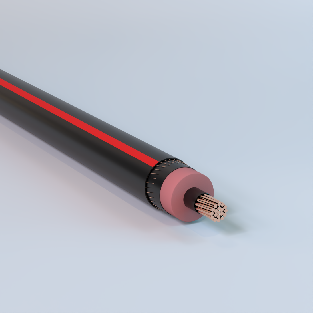
Primary-UD
Underground, EPR Insulation, LLDPE Jacket, Concentric Neutral, 5kV-35kV – Copper
Used for underground primary residential and commercial distribution circuits. May be used in wet or dry locations, installed in underground ducts or direct burial.
Physical Data
| 5 kV EPR Insulated | |||||||||||||||
|---|---|---|---|---|---|---|---|---|---|---|---|---|---|---|---|
| 1/3 Neutral | Full Neutral | ||||||||||||||
| Size AWG or kcmil |
Number of Strands |
Nominal OD Over Insulation |
Number of Wires |
Size | Jacket Thickness |
Approximate Outside Diameter |
Approximate Net Weight |
Size AWG or kcmil |
Number of Strands |
Nominal OD Over Insulation |
Number of Wires |
Size | Jacket Thickness |
Approximate Outside Diameter |
Approximate Net Weight |
| in | AWG | mil | in | lb/kft | in | AWG | mil | in | lb/kft | ||||||
| Copper 100% Insulation Level (90 mil) | |||||||||||||||
| 2 | 7 | 0.5 | 6 | 14 | 50 | 0.81 | 484 | 2 | 7 | 0.5 | 16 | 14 | 50 | 0.81 | 604 |
| 1 | 19 | 0.54 | 7 | 14 | 50 | 0.84 | 564 | 1 | 19 | 0.54 | 13 | 12 | 50 | 0.88 | 747 |
| 1/0 | 19 | 0.58 | 9 | 14 | 50 | 0.88 | 672 | 1/0 | 19 | 0.58 | 16 | 12 | 50 | 0.92 | 889 |
| 2/0 | 19 | 0.63 | 11 | 14 | 50 | 0.93 | 799 | 2/0 | 19 | 0.63 | 13 | 10 | 50 | 1 | 1109 |
| 3/0 | 19 | 0.68 | 14 | 14 | 50 | 0.98 | 963 | 3/0 | 19 | 0.68 | 16 | 10 | 50 | 1.05 | 1331 |
| 4/0 | 19 | 0.73 | 18 | 14 | 50 | 1.03 | 1170 | 4/0 | 19 | 0.73 | 16 | 9 | 50 | 1.14 | 1637 |
| 250 | 37 | 0.79 | 13 | 12 | 50 | 1.12 | 1366 | 250 | 37 | 0.79 | 25 | 10 | 50 | 1.17 | 1910 |
| 350 | 37 | 0.89 | 18 | 12 | 50 | 1.23 | 1815 | 350 | 37 | 0.89 | 22 | 8 | 50 | 1.32 | 2614 |
| 500 | 37 | 1.02 | 17 | 10 | 50 | 1.42 | 2569 | 500 | 37 | 1.02 | 31 | 8 | 50 | 1.47 | 3603 |
| 750 | 61 | 1.21 | 20 | 9 | 80 | 1.7 | 3773 | — | — | — | — | — | — | — | — |
| 1000 | 61 | 1.36 | 26 | 9 | 80 | 1.85 | 4854 | — | — | — | — | — | — | — | — |
| The above data are approximate and subject to normal manufacturing tolerances. Other sizes available upon request. | |||||||||||||||
| 8 kV EPR Insulated | |||||||||||||||
|---|---|---|---|---|---|---|---|---|---|---|---|---|---|---|---|
| 1/3 Neutral | Full Neutral | ||||||||||||||
| Size AWG or kcmil |
Number of Strands |
Nominal OD Over Insulation |
Number of Wires |
Size | Jacket Thickness |
Approximate Outside Diameter |
Approximate Net Weight |
Size AWG or kcmil |
Number of Strands |
Nominal OD Over Insulation |
Number of Wires |
Size | Jacket Thickness |
Approximate Outside Diameter |
Approximate Net Weight |
| in | AWG | mil | in | lb/kft | in | AWG | mil | in | lb/kft | ||||||
| Copper 100% Insulation Level (115 mil) | |||||||||||||||
| 2 | 7 | 0.55 | 6 | 14 | 50 | 0.86 | 517 | 2 | 7 | 0.55 | 16 | 14 | 50 | 0.86 | 637 |
| 1 | 19 | 0.59 | 7 | 14 | 50 | 0.9 | 598 | 1 | 19 | 0.59 | 13 | 12 | 50 | 0.93 | 782 |
| 1/0 | 19 | 0.63 | 9 | 14 | 50 | 0.94 | 708 | 1/0 | 19 | 0.63 | 16 | 12 | 50 | 0.97 | 926 |
| 2/0 | 19 | 0.68 | 11 | 14 | 50 | 0.98 | 837 | 2/0 | 19 | 0.68 | 13 | 10 | 50 | 1.06 | 1149 |
| 3/0 | 19 | 0.73 | 14 | 14 | 50 | 1.03 | 1003 | 3/0 | 19 | 0.73 | 16 | 10 | 50 | 1.11 | 1373 |
| 4/0 | 19 | 0.78 | 18 | 14 | 50 | 1.09 | 1212 | 4/0 | 19 | 0.78 | 16 | 9 | 50 | 1.19 | 1682 |
| 250 | 37 | 0.84 | 13 | 12 | 50 | 1.18 | 1412 | 250 | 37 | 0.84 | 25 | 10 | 50 | 1.22 | 1957 |
| 350 | 37 | 0.94 | 18 | 12 | 50 | 1.28 | 1865 | 350 | 37 | 0.94 | 22 | 8 | 50 | 1.37 | 2667 |
| 500 | 37 | 1.07 | 17 | 10 | 50 | 1.47 | 2627 | 500 | 37 | 1.07 | 31 | 8 | 50 | 1.53 | 3663 |
| 750 | 61 | 1.26 | 20 | 9 | 80 | 1.75 | 3841 | — | — | — | — | — | — | — | — |
| 1000 | 61 | 1.41 | 26 | 9 | 80 | 1.9 | 4929 | — | — | — | — | — | — | — | — |
| The above data are approximate and subject to normal manufacturing tolerances. Other sizes available upon request. | |||||||||||||||
| 15 kV EPR Insulated | |||||||||||||||
|---|---|---|---|---|---|---|---|---|---|---|---|---|---|---|---|
| 1/3 Neutral | Full Neutral | ||||||||||||||
| Size AWG or kcmil |
Number of Strands |
Nominal OD Over Insulation |
Number of Wires |
Size | Jacket Thickness |
Approximate Outside Diameter |
Approximate Net Weight |
Size AWG or kcmil |
Number of Strands |
Nominal OD Over Insulation |
Number of Wires |
Size | Jacket Thickness |
Approximate Outside Diameter |
Approximate Net Weight |
| in | AWG | mil | in | lb/kft | in | AWG | mil | in | lb/kft | ||||||
| Copper 100% Insulation Level (175 mil) | |||||||||||||||
| 2 | 7 | 0.68 | 6 | 14 | 50 | 0.98 | 604 | 2 | 7 | 0.68 | 16 | 14 | 50 | 0.98 | 725 |
| 1 | 19 | 0.71 | 7 | 14 | 50 | 1.02 | 689 | 1 | 19 | 0.71 | 13 | 12 | 50 | 1.05 | 876 |
| 1/0 | 19 | 0.75 | 9 | 14 | 50 | 1.06 | 803 | 1/0 | 19 | 0.75 | 16 | 12 | 50 | 1.09 | 1024 |
| 2/0 | 19 | 0.8 | 11 | 14 | 50 | 1.1 | 937 | 2/0 | 19 | 0.8 | 13 | 10 | 50 | 1.18 | 1255 |
| 3/0 | 19 | 0.85 | 14 | 14 | 50 | 1.15 | 1108 | 3/0 | 19 | 0.85 | 16 | 10 | 50 | 1.23 | 1484 |
| 4/0 | 19 | 0.9 | 18 | 14 | 50 | 1.21 | 1323 | 4/0 | 19 | 0.9 | 16 | 9 | 50 | 1.31 | 1801 |
| 250 | 37 | 0.96 | 13 | 12 | 50 | 1.3 | 1531 | 250 | 37 | 0.96 | 25 | 10 | 50 | 1.34 | 2079 |
| 350 | 37 | 1.06 | 18 | 12 | 50 | 1.42 | 2019 | 350 | 37 | 1.06 | 22 | 8 | 50 | 1.52 | 2830 |
| 500 | 37 | 1.19 | 17 | 10 | 50 | 1.59 | 2775 | 500 | 37 | 1.19 | 31 | 8 | 80 | 1.71 | 3881 |
| 750 | 61 | 1.38 | 20 | 9 | 80 | 1.87 | 4015 | — | — | — | — | — | — | — | — |
| 1000 | 61 | 1.53 | 26 | 9 | 80 | 2.05 | 5167 | — | — | — | — | — | — | — | — |
| Aluminum 100% Insulation Level (175 mil) | |||||||||||||||
| 2 | 1 | 0.65 | 6 | 14 | 50 | 0.95 | 441 | 2 | 1 | 0.65 | 10 | 14 | 50 | 0.95 | 489 |
| 2 | 7 | 0.67 | 6 | 14 | 50 | 0.98 | 459 | 2 | 7 | 0.67 | 10 | 14 | 50 | 0.98 | 507 |
| 1 | 19 | 0.71 | 6 | 14 | 50 | 1.02 | 495 | 1 | 19 | 0.71 | 13 | 14 | 50 | 1.02 | 580 |
| 1/0 | 1 | 0.72 | 6 | 14 | 50 | 1.02 | 512 | 1/0 | 1 | 0.72 | 16 | 14 | 50 | 1.02 | 632 |
| 1/0 | 19 | 0.75 | 6 | 14 | 50 | 1.06 | 537 | 1/0 | 19 | 0.75 | 16 | 14 | 50 | 1.06 | 658 |
| 2/0 | 19 | 0.8 | 7 | 14 | 50 | 1.1 | 600 | 2/0 | 19 | 0.8 | 20 | 14 | 50 | 1.1 | 757 |
| 3/0 | 19 | 0.85 | 9 | 14 | 50 | 1.15 | 684 | 2/0 | 19 | 0.8 | 13 | 12 | 50 | 1.13 | 788 |
| 4/0 | 19 | 0.9 | 11 | 14 | 50 | 1.21 | 781 | 3/0 | 19 | 0.85 | 25 | 14 | 50 | 1.15 | 877 |
| 250 | 37 | 0.96 | 13 | 14 | 50 | 1.26 | 871 | 3/0 | 19 | 0.85 | 16 | 12 | 50 | 1.18 | 907 |
| 300 | 37 | 1.01 | 15 | 14 | 50 | 1.34 | 994 | 4/0 | 19 | 0.9 | 32 | 14 | 50 | 1.21 | 1034 |
| 350 | 37 | 1.06 | 18 | 14 | 50 | 1.39 | 1106 | 4/0 | 19 | 0.9 | 20 | 12 | 50 | 1.24 | 1058 |
| 500 | 37 | 1.19 | 25 | 14 | 50 | 1.52 | 1403 | 4/0 | 19 | 0.9 | 13 | 10 | 50 | 1.28 | 1104 |
| 500 | 37 | 1.19 | 16 | 12 | 50 | 1.55 | 1441 | 250 | 37 | 0.96 | 25 | 12 | 50 | 1.3 | 1220 |
| 750 | 61 | 1.4 | 24 | 12 | 80 | 1.82 | 2033 | 250 | 37 | 0.96 | 16 | 10 | 50 | 1.34 | 1264 |
| 750 | 61 | 1.4 | 15 | 10 | 80 | 1.86 | 2079 | 350 | 37 | 1.06 | 32 | 12 | 50 | 1.42 | 1532 |
| 1000 | 61 | 1.54 | 31 | 12 | 80 | 2 | 2544 | 350 | 37 | 1.06 | 20 | 10 | 50 | 1.46 | 1567 |
| 1000 | 61 | 1.54 | 20 | 10 | 80 | 2.04 | 2614 | 350 | 37 | 1.06 | 16 | 9 | 50 | 1.49 | 1595 |
| 1000 | 61 | 1.54 | 16 | 9 | 80 | 2.07 | 2651 | 500 | 37 | 1.19 | 29 | 10 | 50 | 1.59 | 2060 |
| — | — | — | — | — | — | — | — | 750 | 61 | 1.4 | 28 | 8 | 80 | 1.91 | 3043 |
| — | — | — | — | — | — | — | — | 1000 | 61 | 1.54 | 37 | 8 | 80 | 2.09 | 3868 |
| The above data are approximate and subject to normal manufacturing tolerances. Other sizes available upon request. | |||||||||||||||
| 15 kV EPR Insulated | |||||||||||||||
|---|---|---|---|---|---|---|---|---|---|---|---|---|---|---|---|
| 1/3 Neutral | Full Neutral | ||||||||||||||
| Size AWG or kcmil |
Number of Strands |
Nominal OD Over Insulation |
Number of Wires |
Size | Jacket Thickness |
Approximate Outside Diameter |
Approximate Net Weight |
Size AWG or kcmil |
Number of Strands |
Nominal OD Over Insulation |
Number of Wires |
Size | Jacket Thickness |
Approximate Outside Diameter |
Approximate Net Weight |
| in | AWG | mil | in | lb/kft | in | AWG | mil | in | lb/kft | ||||||
| Copper 133% Insulation Level (220 mil) | |||||||||||||||
| 2 | 7 | 0.77 | 6 | 14 | 50 | 1.07 | 678 | 2 | 7 | 0.77 | 16 | 14 | 50 | 1.07 | 798 |
| 1 | 19 | 0.81 | 7 | 14 | 50 | 1.11 | 766 | 1 | 19 | 0.81 | 13 | 12 | 50 | 1.14 | 955 |
| 1/0 | 19 | 0.85 | 9 | 14 | 50 | 1.15 | 883 | 1/0 | 19 | 0.85 | 16 | 12 | 50 | 1.18 | 1105 |
| 2/0 | 19 | 0.89 | 11 | 14 | 50 | 1.19 | 1020 | 2/0 | 19 | 0.89 | 13 | 10 | 50 | 1.27 | 1342 |
| 3/0 | 19 | 0.94 | 14 | 14 | 50 | 1.24 | 1195 | 3/0 | 19 | 0.94 | 16 | 10 | 50 | 1.32 | 1575 |
| 4/0 | 19 | 1 | 18 | 14 | 50 | 1.3 | 1414 | 4/0 | 19 | 1 | 16 | 9 | 50 | 1.4 | 1898 |
| 250 | 37 | 1.05 | 13 | 12 | 50 | 1.41 | 1653 | 250 | 37 | 1.05 | 25 | 10 | 50 | 1.46 | 2204 |
| 350 | 37 | 1.16 | 18 | 12 | 50 | 1.52 | 2126 | 350 | 37 | 1.16 | 22 | 8 | 50 | 1.61 | 2942 |
| 500 | 37 | 1.28 | 17 | 10 | 80 | 1.75 | 2962 | 500 | 37 | 1.28 | 31 | 8 | 80 | 1.8 | 4007 |
| 750 | 61 | 1.47 | 20 | 9 | 80 | 1.96 | 4154 | — | — | — | — | — | — | — | — |
| 1000 | 61 | 1.62 | 26 | 9 | 80 | 2.14 | 5320 | — | — | — | — | — | — | — | — |
| Aluminum 133% Insulation Level (220 mil) | |||||||||||||||
| 2 | 1 | 0.74 | 6 | 14 | 50 | 1.04 | 511 | 2 | 1 | 0.74 | 10 | 14 | 50 | 1.04 | 560 |
| 2 | 7 | 0.76 | 6 | 14 | 50 | 1.07 | 532 | 2 | 7 | 0.76 | 10 | 14 | 50 | 1.07 | 580 |
| 1 | 19 | 0.8 | 6 | 14 | 50 | 1.11 | 571 | 1 | 19 | 0.8 | 13 | 14 | 50 | 1.11 | 655 |
| 1/0 | 1 | 0.81 | 6 | 14 | 50 | 1.11 | 588 | 1/0 | 1 | 0.81 | 16 | 14 | 50 | 1.11 | 708 |
| 1/0 | 19 | 0.84 | 6 | 14 | 50 | 1.16 | 629 | 1/0 | 19 | 0.84 | 16 | 14 | 50 | 1.15 | 737 |
| 2/0 | 19 | 0.89 | 7 | 14 | 50 | 1.19 | 682 | 2/0 | 19 | 0.89 | 20 | 14 | 50 | 1.19 | 839 |
| 3/0 | 19 | 0.94 | 9 | 14 | 50 | 1.24 | 770 | 2/0 | 19 | 0.89 | 13 | 12 | 50 | 1.22 | 872 |
| 4/0 | 19 | 0.99 | 11 | 14 | 50 | 1.3 | 871 | 3/0 | 19 | 0.94 | 25 | 14 | 50 | 1.24 | 963 |
| 250 | 37 | 1.05 | 13 | 14 | 50 | 1.38 | 989 | 3/0 | 19 | 0.94 | 16 | 12 | 50 | 1.27 | 994 |
| 350 | 37 | 1.15 | 18 | 14 | 50 | 1.48 | 1209 | 4/0 | 19 | 0.99 | 32 | 14 | 50 | 1.3 | 1124 |
| 500 | 37 | 1.28 | 25 | 14 | 50 | 1.61 | 1517 | 4/0 | 19 | 0.99 | 20 | 12 | 50 | 1.33 | 1149 |
| 500 | 37 | 1.28 | 16 | 12 | 80 | 1.7 | 1623 | 4/0 | 19 | 0.99 | 13 | 10 | 50 | 1.37 | 1199 |
| 750 | 61 | 1.49 | 24 | 12 | 80 | 1.91 | 2167 | 250 | 37 | 1.05 | 25 | 12 | 50 | 1.41 | 1341 |
| 750 | 61 | 1.49 | 15 | 10 | 80 | 1.95 | 2216 | 250 | 37 | 1.05 | 16 | 10 | 50 | 1.45 | 1388 |
| 1000 | 61 | 1.64 | 31 | 12 | 80 | 2.09 | 2692 | 350 | 37 | 1.15 | 32 | 12 | 50 | 1.51 | 1637 |
| 1000 | 61 | 1.64 | 20 | 10 | 80 | 2.13 | 2764 | 350 | 37 | 1.15 | 20 | 10 | 50 | 1.55 | 1674 |
| 1000 | 61 | 1.64 | 16 | 9 | 80 | 2.16 | 2803 | 350 | 37 | 1.15 | 16 | 9 | 50 | 1.58 | 1704 |
| The above data are approximate and subject to normal manufacturing tolerances. Other sizes available upon request. | |||||||||||||||
| 25 kV EPR Insulated | |||||||||||||||
|---|---|---|---|---|---|---|---|---|---|---|---|---|---|---|---|
| 1/3 Neutral | Full Neutral | ||||||||||||||
| Size AWG or kcmil |
Number of Strands |
Nominal OD Over Insulation |
Number of Wires |
Size | Jacket Thickness |
Approximate Outside Diameter |
Approximate Net Weight |
Size AWG or kcmil |
Number of Strands |
Nominal OD Over Insulation |
Number of Wires |
Size | Jacket Thickness |
Approximate Outside Diameter |
Approximate Net Weight |
| in | AWG | mil | in | lb/kft | in | AWG | mil | in | lb/kft | ||||||
| Copper 100% Insulation Level (260 mil) | |||||||||||||||
| 1 | 19 | 0.89 | 7 | 14 | 50 | 1.19 | 840 | 1 | 19 | 0.89 | 13 | 12 | 50 | 1.23 | 1030 |
| 1/0 | 19 | 0.93 | 9 | 14 | 50 | 1.23 | 959 | 1/0 | 19 | 0.93 | 16 | 12 | 50 | 1.27 | 1184 |
| 2/0 | 19 | 0.97 | 11 | 14 | 50 | 1.28 | 1099 | 2/0 | 19 | 0.97 | 13 | 10 | 50 | 1.35 | 1426 |
| 3/0 | 19 | 1.02 | 14 | 14 | 50 | 1.35 | 1301 | 3/0 | 19 | 1.02 | 16 | 10 | 50 | 1.42 | 1687 |
| 4/0 | 19 | 1.08 | 18 | 14 | 50 | 1.4 | 1525 | 4/0 | 19 | 1.08 | 16 | 9 | 50 | 1.51 | 2016 |
| 250 | 37 | 1.13 | 13 | 12 | 50 | 1.49 | 1747 | 250 | 37 | 1.13 | 25 | 10 | 50 | 1.54 | 2300 |
| 350 | 37 | 1.24 | 18 | 12 | 50 | 1.6 | 2227 | 350 | 37 | 1.24 | 22 | 8 | 80 | 1.75 | 3116 |
| 500 | 37 | 1.37 | 17 | 10 | 80 | 1.83 | 3077 | 500 | 37 | 1.37 | 31 | 8 | 80 | 1.88 | 4124 |
| 750 | 61 | 1.56 | 20 | 9 | 80 | 2.08 | 4333 | — | — | — | — | — | — | — | — |
| 1000 | 61 | 1.7 | 26 | 9 | 80 | 2.23 | 5461 | — | — | — | — | — | — | — | — |
| Aluminum 100% Insulation Level (260 mil) | |||||||||||||||
| 1 | 19 | 0.88 | 6 | 14 | 50 | 1.19 | 644 | 1 | 19 | 0.88 | 13 | 14 | 50 | 1.19 | 728 |
| 1/0 | 1 | 0.89 | 6 | 14 | 50 | 1.19 | 661 | 1/0 | 1 | 0.89 | 16 | 14 | 50 | 1.19 | 781 |
| 1/0 | 19 | 0.92 | 6 | 14 | 50 | 1.23 | 692 | 1/0 | 19 | 0.92 | 16 | 14 | 50 | 1.23 | 812 |
| 2/0 | 19 | 0.97 | 7 | 14 | 50 | 1.27 | 760 | 2/0 | 19 | 0.97 | 20 | 14 | 50 | 1.27 | 917 |
| 3/0 | 19 | 1.02 | 9 | 14 | 50 | 1.34 | 875 | 2/0 | 19 | 0.97 | 13 | 12 | 50 | 1.3 | 952 |
| 4/0 | 19 | 1.07 | 11 | 14 | 50 | 1.4 | 981 | 3/0 | 19 | 1.02 | 25 | 14 | 50 | 1.34 | 1068 |
| 250 | 37 | 1.13 | 13 | 14 | 50 | 1.46 | 1080 | 3/0 | 19 | 1.02 | 16 | 12 | 50 | 1.38 | 1102 |
| 350 | 37 | 1.23 | 18 | 14 | 50 | 1.56 | 1307 | 4/0 | 19 | 1.07 | 32 | 14 | 50 | 1.4 | 1234 |
| 500 | 37 | 1.36 | 25 | 14 | 80 | 1.75 | 1692 | 4/0 | 19 | 1.07 | 20 | 12 | 50 | 1.43 | 1261 |
| 500 | 37 | 1.36 | 16 | 12 | 80 | 1.78 | 1735 | 4/0 | 19 | 1.07 | 13 | 10 | 50 | 1.48 | 1313 |
| 750 | 61 | 1.57 | 24 | 12 | 80 | 2.02 | 2340 | 250 | 37 | 1.13 | 25 | 12 | 50 | 1.49 | 1433 |
| 750 | 61 | 1.57 | 15 | 10 | 80 | 2.06 | 2392 | 250 | 37 | 1.13 | 16 | 10 | 50 | 1.53 | 1482 |
| 1000 | 61 | 1.72 | 31 | 12 | 80 | 2.17 | 2829 | 350 | 37 | 1.23 | 32 | 12 | 50 | 1.59 | 1736 |
| 1000 | 61 | 1.72 | 20 | 10 | 80 | 2.21 | 2903 | 350 | 37 | 1.23 | 20 | 10 | 80 | 1.7 | 1843 |
| 1000 | 61 | 1.72 | 16 | 9 | 80 | 2.24 | 2944 | 350 | 37 | 1.23 | 16 | 9 | 80 | 1.72 | 1875 |
| — | — | — | — | — | — | — | — | 500 | 37 | 1.36 | 29 | 10 | 80 | 1.83 | 2361 |
| — | — | — | — | — | — | — | — | 750 | 61 | 1.57 | 28 | 8 | 80 | 2.12 | 3362 |
| — | — | — | — | — | — | — | — | 1000 | 61 | 1.72 | 37 | 8 | 80 | 2.27 | 4163 |
| The above data are approximate and subject to normal manufacturing tolerances. Other sizes available upon request. | |||||||||||||||
| 25 kV EPR Insulated | |||||||||||||||
|---|---|---|---|---|---|---|---|---|---|---|---|---|---|---|---|
| 1/3 Neutral | Full Neutral | ||||||||||||||
| Size AWG or kcmil |
Number of Strands |
Nominal OD Over Insulation |
Number of Wires |
Size | Jacket Thickness |
Approximate Outside Diameter |
Approximate Net Weight |
Size AWG or kcmil |
Number of Strands |
Nominal OD Over Insulation |
Number of Wires |
Size | Jacket Thickness |
Approximate Outside Diameter |
Approximate Net Weight |
| in | AWG | mil | in | lb/kft | i n | AWG | mil | in | lb/kft | ||||||
| Copper 133% Insulation Level (320 mil) | |||||||||||||||
| 1 | 19 | 1.01 | 7 | 14 | 50 | 1.31 | 961 | 1 | 19 | 1.01 | 13 | 12 | 50 | 1.35 | 1154 |
| 1/0 | 19 | 1.05 | 9 | 14 | 50 | 1.38 | 1109 | 1/0 | 19 | 1.05 | 16 | 12 | 50 | 1.41 | 1337 |
| 2/0 | 19 | 1.09 | 11 | 14 | 50 | 1.42 | 1254 | 2/0 | 19 | 1.09 | 13 | 10 | 50 | 1.5 | 1588 |
| 3/0 | 19 | 1.14 | 14 | 14 | 50 | 1.47 | 1439 | 3/0 | 19 | 1.14 | 16 | 10 | 50 | 1.55 | 1830 |
| 4/0 | 19 | 1.2 | 18 | 14 | 50 | 1.53 | 1668 | 4/0 | 19 | 1.2 | 16 | 9 | 80 | 1.69 | 2232 |
| 250 | 37 | 1.26 | 13 | 12 | 50 | 1.62 | 1898 | 250 | 37 | 1.26 | 25 | 10 | 80 | 1.72 | 2522 |
| 350 | 37 | 1.36 | 18 | 12 | 80 | 1.78 | 2458 | 350 | 37 | 1.36 | 22 | 8 | 80 | 1.88 | 3290 |
| 500 | 37 | 1.49 | 17 | 10 | 80 | 1.95 | 3260 | 500 | 37 | 1.49 | 31 | 8 | 80 | 2.01 | 4311 |
| 750 | 61 | 1.68 | 20 | 9 | 80 | 2.2 | 4540 | — | — | — | — | — | — | — | — |
| 1000 | 61 | 1.83 | 26 | 9 | 80 | 2.35 | 5683 | — | — | — | — | — | — | — | — |
| Aluminum 133% Insulation Level (320 mil) | |||||||||||||||
| 1/0 | 19 | 1.05 | 6 | 14 | 50 | 1.37 | 839 | 1/0 | 19 | 1.05 | 16 | 14 | 50 | 1.37 | 959 |
| 2/0 | 19 | 1.09 | 7 | 14 | 50 | 1.42 | 913 | 2/0 | 19 | 1.09 | 20 | 14 | 50 | 1.42 | 1070 |
| 3/0 | 19 | 1.14 | 9 | 14 | 50 | 1.47 | 1010 | 2/0 | 19 | 1.09 | 13 | 12 | 50 | 1.45 | 1108 |
| 4/0 | 19 | 1.2 | 11 | 14 | 50 | 1.52 | 1122 | 3/0 | 19 | 1.14 | 25 | 14 | 50 | 1.47 | 1203 |
| 250 | 37 | 1.25 | 13 | 14 | 50 | 1.58 | 1226 | 3/0 | 19 | 1.14 | 16 | 12 | 50 | 1.5 | 1239 |
| 350 | 37 | 1.35 | 18 | 14 | 80 | 1.74 | 1533 | 4/0 | 19 | 1.2 | 32 | 14 | 50 | 1.52 | 1375 |
| 500 | 37 | 1.48 | 25 | 14 | 80 | 1.87 | 1867 | 4/0 | 19 | 1.2 | 20 | 12 | 50 | 1.55 | 1405 |
| 500 | 37 | 1.48 | 16 | 12 | 80 | 1.91 | 1912 | 4/0 | 19 | 1.2 | 13 | 10 | 50 | 1.6 | 1460 |
| 750 | 61 | 1.69 | 24 | 12 | 80 | 2.14 | 2540 | 250 | 37 | 1.25 | 25 | 12 | 50 | 1.61 | 1583 |
| 750 | 61 | 1.69 | 15 | 10 | 80 | 2.18 | 2596 | 250 | 37 | 1.25 | 16 | 10 | 80 | 1.72 | 1703 |
| 1000 | 61 | 1.84 | 31 | 12 | 80 | 2.29 | 3045 | 350 | 37 | 1.35 | 32 | 12 | 80 | 1.78 | 1966 |
| 1000 | 61 | 1.84 | 20 | 10 | 80 | 2.33 | 3123 | 350 | 37 | 1.35 | 20 | 10 | 80 | 1.82 | 2011 |
| 1000 | 61 | 1.84 | 16 | 9 | 80 | 2.36 | 3165 | 350 | 37 | 1.35 | 16 | 9 | 80 | 1.84 | 2045 |
| — | — | — | — | — | — | — | — | 500 | 37 | 1.48 | 29 | 10 | 80 | 1.95 | 2541 |
| The above data are approximate and subject to normal manufacturing tolerances. Other sizes available upon request. | |||||||||||||||
| 35 kV EPR Insulated | |||||||||||||||
|---|---|---|---|---|---|---|---|---|---|---|---|---|---|---|---|
| 1/3 Neutral | Full Neutral | ||||||||||||||
| Size AWG or kcmil |
Number of Strands |
Nominal OD Over Insulation |
Number of Wires |
Size | Jacket Thickness |
Approximate Outside Diameter |
Approximate Net Weight |
Size AWG or kcmil |
Number of Strands |
Nominal OD Over Insulation |
Number of Wires |
Size | Jacket Thickness |
Approximate Outside Diameter |
Approximate Net Weight |
| in | AWG | mil | in | lb/kft | in | AWG | mil | in | lb/kft | ||||||
| Copper 100% Insulation Level (345 mil) | |||||||||||||||
| 1/0 | 19 | 1.1 | 9 | 14 | 50 | 1.43 | 1166 | 1/0 | 19 | 1.1 | 16 | 12 | 50 | 1.46 | 1395 |
| 2/0 | 19 | 1.15 | 11 | 14 | 50 | 1.47 | 1313 | 2/0 | 19 | 1.15 | 13 | 10 | 50 | 1.55 | 1649 |
| 3/0 | 19 | 1.2 | 14 | 14 | 50 | 1.52 | 1499 | 3/0 | 19 | 1.2 | 16 | 10 | 50 | 1.6 | 1893 |
| 4/0 | 19 | 1.25 | 18 | 14 | 50 | 1.58 | 1731 | 4/0 | 19 | 1.25 | 16 | 9 | 80 | 1.74 | 2301 |
| 250 | 37 | 1.31 | 13 | 12 | 80 | 1.73 | 2032 | 250 | 37 | 1.31 | 25 | 10 | 80 | 1.77 | 2592 |
| 350 | 37 | 1.41 | 18 | 12 | 80 | 1.83 | 2531 | 350 | 37 | 1.41 | 22 | 8 | 80 | 1.93 | 3366 |
| 500 | 37 | 1.54 | 17 | 10 | 80 | 2.04 | 3388 | 500 | 37 | 1.54 | 31 | 8 | 80 | 2.09 | 4443 |
| 750 | 61 | 1.73 | 20 | 9 | 80 | 2.25 | 4630 | — | — | — | — | — | — | — | — |
| 1000 | 61 | 1.88 | 26 | 9 | 80 | 2.4 | 5779 | — | — | — | — | — | — | — | — |
| Aluminum 100% Insulation Level (345 mil) | |||||||||||||||
| 1/0 | 1 | 1.06 | 6 | 14 | 50 | 1.38 | 858 | 1/0 | 1 | 1.06 | 16 | 14 | 50 | 1.38 | 979 |
| 1/0 | 19 | 1.1 | 6 | 14 | 50 | 1.42 | 895 | 1/0 | 19 | 1.1 | 16 | 14 | 50 | 1.42 | 1015 |
| 2/0 | 19 | 1.14 | 7 | 14 | 50 | 1.47 | 971 | 2/0 | 19 | 1.14 | 20 | 14 | 50 | 1.47 | 1127 |
| 3/0 | 19 | 1.19 | 9 | 14 | 50 | 1.52 | 1070 | 2/0 | 19 | 1.14 | 13 | 12 | 50 | 1.5 | 1167 |
| 4/0 | 19 | 1.25 | 11 | 14 | 50 | 1.57 | 1184 | 3/0 | 19 | 1.19 | 25 | 14 | 50 | 1.52 | 1263 |
| 250 | 37 | 1.3 | 13 | 14 | 80 | 1.69 | 1358 | 3/0 | 19 | 1.19 | 16 | 12 | 50 | 1.55 | 1300 |
| 350 | 37 | 1.4 | 18 | 14 | 80 | 1.79 | 1604 | 4/0 | 19 | 1.25 | 32 | 14 | 50 | 1.57 | 1437 |
| 500 | 37 | 1.53 | 25 | 14 | 80 | 1.95 | 1989 | 4/0 | 19 | 1.25 | 20 | 12 | 50 | 1.61 | 1468 |
| 500 | 37 | 1.53 | 16 | 12 | 80 | 1.99 | 2036 | 4/0 | 19 | 1.25 | 13 | 10 | 80 | 1.71 | 1592 |
| 750 | 61 | 1.74 | 24 | 12 | 80 | 2.19 | 2628 | 250 | 37 | 1.3 | 25 | 12 | 80 | 1.73 | 1716 |
| 750 | 61 | 1.74 | 15 | 10 | 80 | 2.24 | 2684 | 250 | 37 | 1.3 | 16 | 10 | 80 | 1.77 | 1772 |
| 1000 | 61 | 1.89 | 31 | 12 | 80 | 2.34 | 3139 | 350 | 37 | 1.4 | 32 | 12 | 80 | 1.83 | 2038 |
| 1000 | 61 | 1.89 | 20 | 10 | 80 | 2.38 | 3217 | 350 | 37 | 1.4 | 20 | 10 | 80 | 1.87 | 2084 |
| 1000 | 61 | 1.89 | 16 | 9 | 80 | 2.41 | 3260 | 350 | 37 | 1.4 | 16 | 9 | 80 | 1.89 | 2119 |
| — | — | — | — | — | — | — | — | 500 | 37 | 1.53 | 29 | 10 | 80 | 2.03 | 2667 |
| — | — | — | — | — | — | — | — | 750 | 61 | 1.74 | 28 | 8 | 80 | 2.29 | 3661 |
| — | — | — | — | — | — | — | — | 1000 | 61 | 1.89 | 37 | 8 | 80 | 2.44 | 4483 |
| The above data are approximate and subject to normal manufacturing tolerances. Other sizes available upon request. | |||||||||||||||
| 35 kV EPR Insulated | |||||||||||||||
|---|---|---|---|---|---|---|---|---|---|---|---|---|---|---|---|
| 1/3 Neutral | Full Neutral | ||||||||||||||
| Size AWG or kcmil |
Number of Strands |
Nominal OD Over Insulation |
Number of Wires |
Size | Jacket Thickness |
Approximate Outside Diameter |
Approximate Net Weight |
Size AWG or kcmil |
Number of Strands |
Nominal OD Over Insulation |
Number of Wires |
Size | Jacket Thickness |
Approximate Outside Diameter |
Approximate Net Weight |
| in | AWG | mil | in | lb/kft | in | AWG | mil | in | lb/kft | ||||||
| Copper 133% Insulation Level (420 mil) | |||||||||||||||
| 1/0 | 19 | 1.25 | 9 | 14 | 50 | 1.58 | 1349 | 1/0 | 19 | 1.25 | 16 | 12 | 50 | 1.61 | 1581 |
| 2/0 | 19 | 1.3 | 11 | 14 | 50 | 1.63 | 1502 | 2/0 | 19 | 1.3 | 13 | 10 | 80 | 1.76 | 1914 |
| 3/0 | 19 | 1.35 | 14 | 14 | 80 | 1.74 | 1762 | 3/0 | 19 | 1.35 | 16 | 10 | 80 | 1.81 | 2166 |
| 4/0 | 19 | 1.4 | 18 | 14 | 80 | 1.79 | 2004 | 4/0 | 19 | 1.4 | 16 | 9 | 80 | 1.89 | 2519 |
| 250 | 37 | 1.46 | 13 | 12 | 80 | 1.88 | 2251 | 250 | 37 | 1.46 | 25 | 10 | 80 | 1.93 | 2815 |
| 350 | 37 | 1.56 | 18 | 12 | 80 | 2.02 | 2811 | 350 | 37 | 1.56 | 22 | 8 | 80 | 2.11 | 3658 |
| 500 | 37 | 1.69 | 17 | 10 | 80 | 2.19 | 3645 | 500 | 37 | 1.69 | 31 | 8 | 80 | 2.24 | 4704 |
| 750 | 61 | 1.88 | 20 | 9 | 80 | 2.4 | 4912 | — | — | — | — | — | — | — | — |
| 1000 | 61 | 2.03 | 26 | 9 | 80 | 2.55 | 6081 | — | — | — | — | — | — | — | — |
| Aluminum 133% Insulation Level (420 mil) | |||||||||||||||
| 1/0 | 19 | 1.25 | 6 | 14 | 50 | 1.57 | 1076 | 1/0 | 19 | 1.25 | 16 | 14 | 50 | 1.57 | 1196 |
| 2/0 | 19 | 1.29 | 7 | 14 | 50 | 1.62 | 1157 | 2/0 | 19 | 1.29 | 20 | 14 | 80 | 1.68 | 1380 |
| 3/0 | 19 | 1.34 | 9 | 14 | 80 | 1.73 | 1331 | 2/0 | 19 | 1.29 | 13 | 12 | 80 | 1.71 | 1424 |
| 4/0 | 19 | 1.4 | 11 | 14 | 80 | 1.79 | 1454 | 3/0 | 19 | 1.34 | 25 | 14 | 80 | 1.73 | 1524 |
| 250 | 37 | 1.45 | 13 | 14 | 80 | 1.84 | 1571 | 3/0 | 19 | 1.34 | 16 | 12 | 80 | 1.76 | 1566 |
| 350 | 37 | 1.56 | 18 | 14 | 80 | 1.98 | 1876 | 4/0 | 19 | 1.4 | 32 | 14 | 80 | 1.79 | 1707 |
| 500 | 37 | 1.68 | 25 | 14 | 80 | 2.11 | 2235 | 4/0 | 19 | 1.4 | 20 | 12 | 80 | 1.82 | 1743 |
| 500 | 37 | 1.68 | 16 | 12 | 80 | 2.14 | 2285 | 4/0 | 19 | 1.4 | 13 | 10 | 80 | 1.86 | 1805 |
| 750 | 61 | 1.89 | 24 | 12 | 80 | 2.34 | 2902 | 250 | 37 | 1.45 | 25 | 12 | 80 | 1.88 | 1933 |
| 750 | 61 | 1.89 | 15 | 10 | 80 | 2.39 | 2963 | 250 | 37 | 1.45 | 16 | 10 | 80 | 1.92 | 1992 |
| 1000 | 61 | 2.04 | 16 | 9 | 80 | 2.56 | 3560 | 350 | 37 | 1.56 | 32 | 12 | 80 | 2.01 | 2314 |
| — | — | — | — | — | — | — | — | 350 | 37 | 1.56 | 20 | 10 | 80 | 2.05 | 2365 |
| — | — | — | — | — | — | — | — | 350 | 37 | 1.56 | 16 | 9 | 80 | 2.08 | 2403 |
| — | — | — | — | — | — | — | — | 500 | 37 | 1.68 | 29 | 10 | 80 | 2.18 | 2920 |
| The above data are approximate and subject to normal manufacturing tolerances. Other sizes available upon request. | |||||||||||||||
Ampacity Data
| Ampacity 100% and 133% Insulation Levels | ||||||||
|---|---|---|---|---|---|---|---|---|
| Size AWG or kcmil |
Copper | Aluminum | ||||||
| 5 – 15 kV | 25 – 46 kV | 5 – 15 kV | 25 – 46 kV | |||||
| 1/3 Neutral | Full Neutral | 1/3 Neutral | Full Neutral | 1/3 Neutral | Full Neutral | 1/3 Neutral | Full Neutral | |
| amp | amp | amp | amp | |||||
| 2 | 160 | 160 | – | – | 125 | 125 | – | – |
| 1 | 187 | 185 | 189 | 188 | 146 | 145 | 147 | 147 |
| 1/0 | 212 | 210 | 214 | 212 | 166 | 165 | 167 | 167 |
| 2/0 | 241 | 238 | 248 | 245 | 189 | 188 | 194 | 193 |
| 3/0 | 273 | 268 | 281 | 276 | 214 | 213 | 220 | 218 |
| 4/0 | 309 | 300 | 317 | 309 | 244 | 241 | 250 | 247 |
| 250 | 336 | – | 344 | – | 266 | – | 273 | – |
| 350 | 398 | – | 407 | – | 320 | – | 326 | – |
| 500 | 476 | – | 476 | – | 394 | – | 392 | – |
| 750 | 547 | – | 565 | – | 476 | – | 486 | – |
| 1000 | 620 | – | 625 | – | 550 | – | 556 | – |
|
1/6 Neutral | Full Neutral | 1/6 Neutral | Full Neutral | 1/6 Neutral | Full Neutral | 1/6 Neutral | Full Neutral |
| 1000 | 658 | – | 658 | – | 580 | – | 573 | – |
| † Ampacities are based on the following: Copper: Three shielded single insulated Copper conductors in buried ducts, single circuit, 25 °C ambient earth temperature, 75% load factor, 90 RHO and 90 °C conductor temperature (IEEE Std. 835). Aluminum: Three shielded single insulated Aluminum conductors in buried ducts, single circuit, 25 °C ambient earth temperature, 75% load factor, 90 RHO and 90 °C conductor temperature (IEEE Std. 835). |
||||||||
| Rating Voltage |
Minimum Size AWG |
|---|---|
| 5 kV | 8 |
| 8 kV | 6 |
| 15 kV | 2 |
| 25 kV | 1 |
| 35 kV | 1/0 |
Primary-UD
Underground, EPR Insulation, LLDPE Jacket, Flat Strap Neutral, 15kV-35kV – Copper
Used for underground primary residential and commercial distribution circuits. May be used in wet or dry locations, installed in underground ducts or direct burial.
Physical Data
| 15 kV EPR Insulated | |||||||||||
|---|---|---|---|---|---|---|---|---|---|---|---|
| Size AWG or kcmil |
Number of Strands |
100% Insulation Level (175 mils) | 133% Insulation Level (220 mils) | ||||||||
| Flat Straps | Jacket Thickness |
Approximate Outside Diameter |
Approximate Net Weight |
Flat Straps | Jacket Thickness |
Approximate Outside Diameter |
Approximate Net Weight |
||||
| No. of Wires | Dimensions | mil | in | lb/kft | No. of Wires | Dimensions | mil | in | lb/kft | ||
| mil | mil | mil | mil | ||||||||
| 4/0 | 19 | 12 | 20 x 175 | 50 | 1.08 | 1185 | 12 | 20 x 175 | 50 | 1.17 | 1267 |
| 250 | 37 | 14 | 20 x 175 | 50 | 1.12 | 1353 | 14 | 20 x 175 | 50 | 1.22 | 1439 |
| 350 | 37 | 14 | 20 x 175 | 50 | 1.25 | 1742 | 14 | 20 x 175 | 50 | 1.35 | 1838 |
| 500 | 37 | 14 | 20 X 175 | 50 | 1.37 | 2270 | 14 | 20 x 175 | 50 | 1.47 | 2376 |
| 750 | 61 | 16 | 20 x 175 | 50 | 1.56 | 3176 | 16 | 20 x 175 | 50 | 1.65 | 3295 |
| 1000 | 61 | 16 | 20 x 175 | 50 | 1.71 | 4041 | 16 | 20 x 175 | 50 | 1.83 | 4214 |
| The above data are approximate and subject to normal manufacturing tolerances. Other sizes available upon request. | |||||||||||
| 25 kV EPR Insulated | ||||||
|---|---|---|---|---|---|---|
| 100% Insulation Level (260 mils) | ||||||
| Size AWG or kcmil |
Number of Strands |
Flat Straps | Jacket Thickness |
Approximate Outside Diameter |
Approximate Net Weight |
|
| Number of Wires | Dimensions | mil | in | lb/kft | ||
| mil | mil | |||||
| 4/0 | 19 | 12 | 20 x 175 | 50 | 1.27 | 1368 |
| 250 | 37 | 14 | 20 x 175 | 50 | 1.32 | 1544 |
| 350 | 37 | 14 | 20 x 175 | 50 | 1.43 | 1929 |
| 500 | 37 | 14 | 20 x 175 | 50 | 1.55 | 2475 |
| 750 | 61 | 16 | 20 x 175 | 50 | 1.73 | 3406 |
| The above data are approximate and subject to normal manufacturing tolerances. Other sizes available upon request. | ||||||
| 35 kV EPR Insulated | ||||||
|---|---|---|---|---|---|---|
| 100% Insulation Level (345 mils) | ||||||
| Size AWG or kcmil |
Number of Strands |
Flat Straps | Jacket Thickness |
Approximate Outside Diameter |
Approximate Net Weight |
|
| Number of Wires | Dimensions | mil | in | lb/kft | ||
| mil | mil | |||||
| 4/0 | 19 | 12 | 20 x 175 | 50 | 1.45 | 1558 |
| 250 | 37 | 14 | 20 x 175 | 50 | 1.49 | 1741 |
| 350 | 37 | 14 | 20 x 175 | 50 | 1.6 | 2142 |
| 500 | 37 | 14 | 20 x 175 | 50 | 1.72 | 2705 |
| 750 | 61 | 16 | 20 x 175 | 50 | 1.93 | 3707 |
| 1000 | 61 | 16 | 20 x 175 | 50 | 2.08 | 4620 |
| The above data are approximate and subject to normal manufacturing tolerances. Other sizes available upon request. | ||||||
Ampacity Data
| Ampacity 100% and 133% Insulation Levels | ||||||||
|---|---|---|---|---|---|---|---|---|
| Size AWG or kcmil |
Copper | Aluminum | ||||||
| 5 – 15 kV | 25 – 46 kV | 5 – 15 kV | 25 – 46 kV | |||||
| 1/3 Neutral | Full Neutral | 1/3 Neutral | Full Neutral | 1/3 Neutral | Full Neutral | 1/3 Neutral | Full Neutral | |
| amp | amp | amp | amp | |||||
| 2 | 160 | 160 | – | – | 125 | 125 | – | – |
| 1 | 187 | 185 | 189 | 188 | 146 | 145 | 147 | 147 |
| 1/0 | 212 | 210 | 214 | 212 | 166 | 165 | 167 | 167 |
| 2/0 | 241 | 238 | 248 | 245 | 189 | 188 | 194 | 193 |
| 3/0 | 273 | 268 | 281 | 276 | 214 | 213 | 220 | 218 |
| 4/0 | 309 | 300 | 317 | 309 | 244 | 241 | 250 | 247 |
| 250 | 336 | – | 344 | – | 266 | – | 273 | – |
| 350 | 398 | – | 407 | – | 320 | – | 326 | – |
| 500 | 476 | – | 476 | – | 394 | – | 392 | – |
| 750 | 547 | – | 565 | – | 476 | – | 486 | – |
| 1000 | 620 | – | 625 | – | 550 | – | 556 | – |
|
1/6 Neutral | Full Neutral | 1/6 Neutral | Full Neutral | 1/6 Neutral | Full Neutral | 1/6 Neutral | Full Neutral |
| 1000 | 658 | – | 658 | – | 580 | – | 573 | – |
| † Ampacities are based on the following: Copper: Three shielded single insulated Copper conductors in buried ducts, single circuit, 25 °C ambient earth temperature, 75% load factor, 90 RHO and 90 °C conductor temperature (IEEE Std. 835). Aluminum: Three shielded single insulated Aluminum conductors in buried ducts, single circuit, 25 °C ambient earth temperature, 75% load factor, 90 RHO and 90 °C conductor temperature (IEEE Std. 835). |
||||||||
| Rating Voltage |
Minimum Size AWG |
|---|---|
| 5 kV | 8 |
| 8 kV | 6 |
| 15 kV | 2 |
| 25 kV | 1 |
| 35 kV | 1/0 |
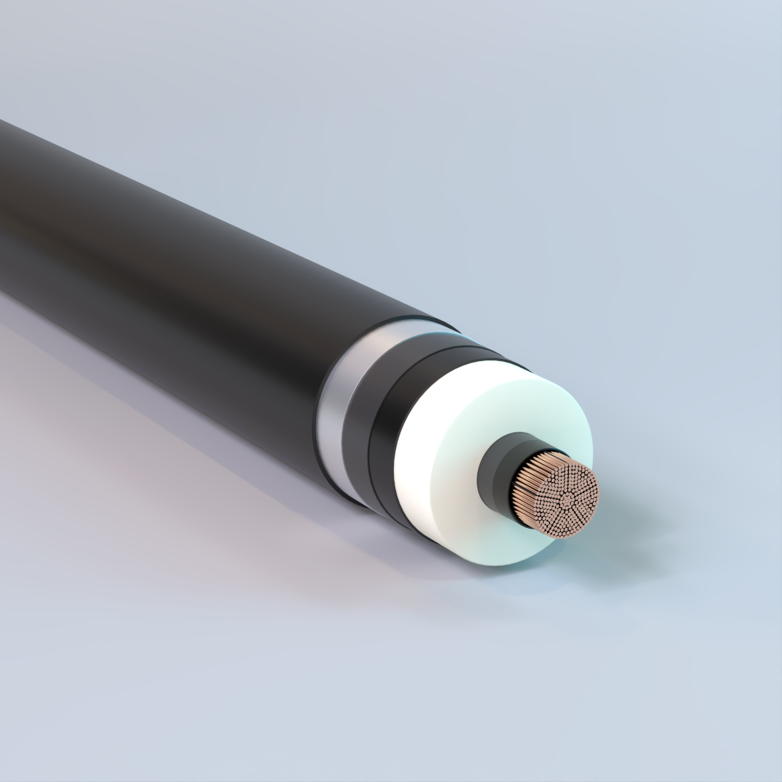
High Voltage, Smooth Aluminum Shield/Sheath
XLPE Insulation, HDPE Jacket, 69kV-138kV – Copper
Used for transmission and distribution circuits in cities with high load densities. Also, for industrial and commercial installations. May be installed in wet or dry locations indoors or outdoors in conduit and underground ducts.
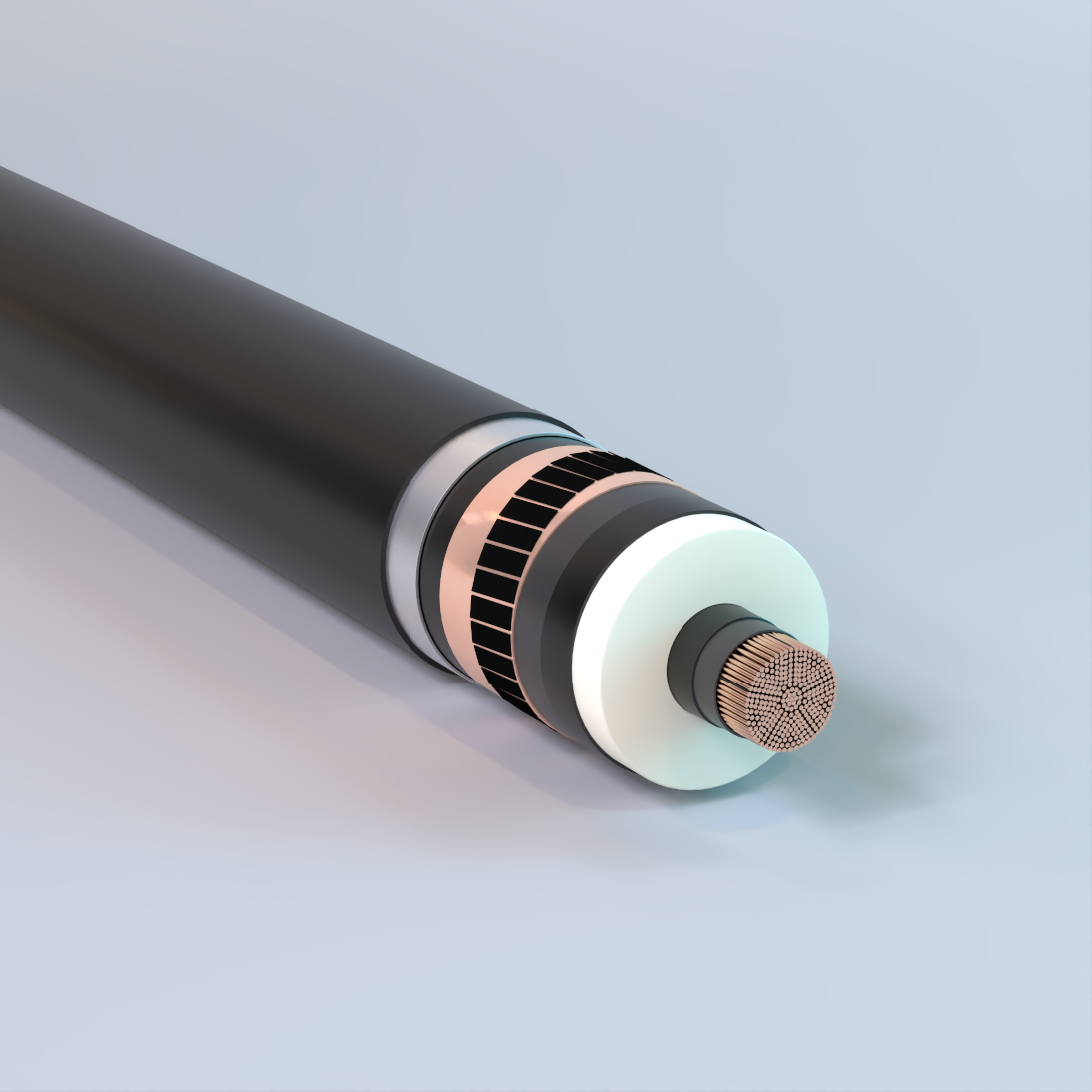
High Voltage, Wire and Tape Shield
XLPE Insulation, HDPE Jacket, 69kV-138kV – Copper
Used for transmission and distribution circuits in cities with high load densities. Also, for industrial and commercial installations. May be installed in wet or dry locations indoors or outdoors in conduit and underground ducts.
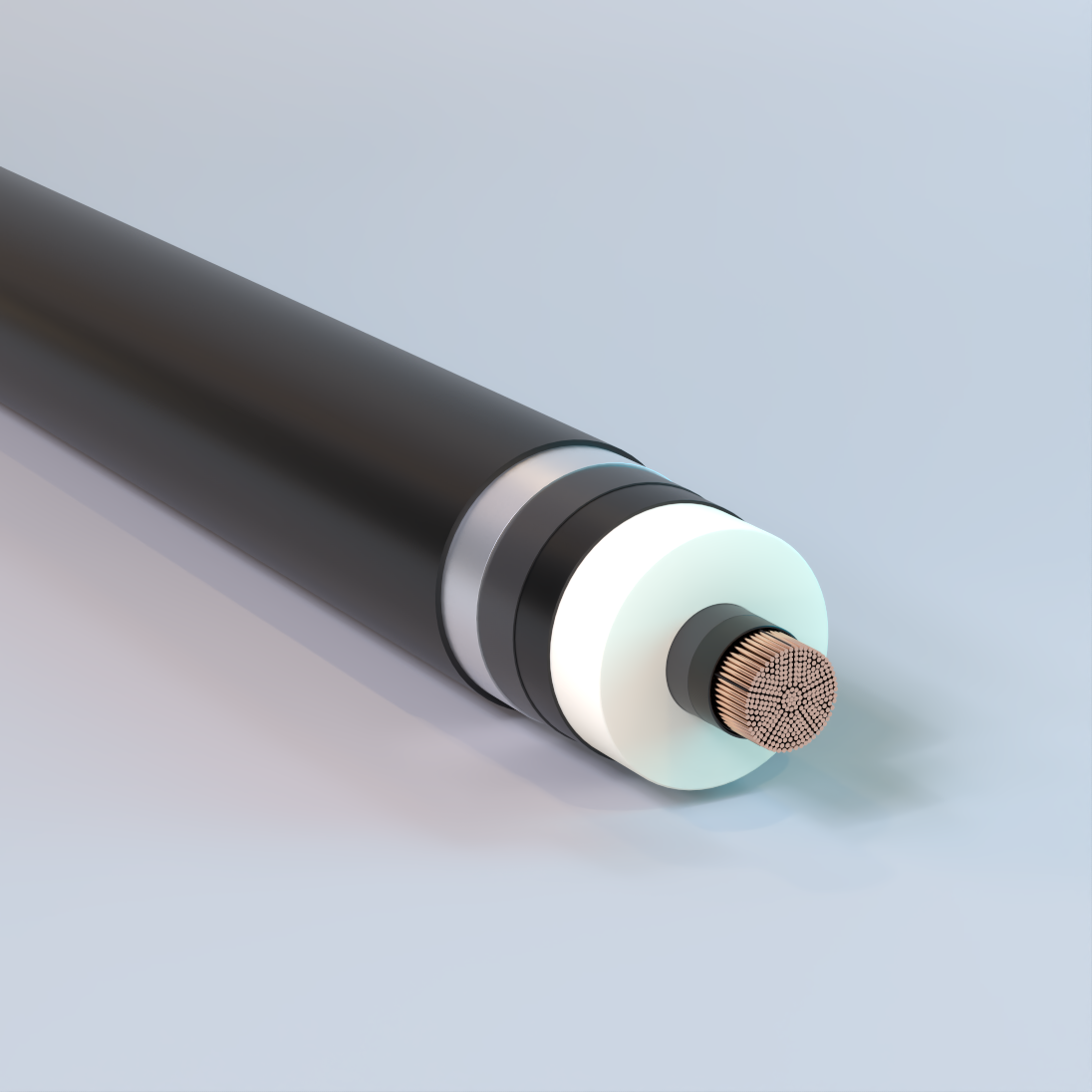
Extra High Voltage, Smooth Aluminum Shield/Sheath
XLPE Insulation, HDPE Jacket, 230kV – Copper
Used for transmission systems in urban and industrial installations with high load density. May be installed in wet or dry locations indoors or outdoors in conduit and underground ducts.
Composite Conductor
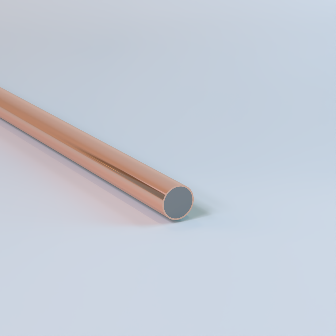
Bare Copper-Clad Steel (CCS) Conductor
Solid (Single End), Drawn Steel Alloy (DSA) Core, Metallurgically Bonded Copper Cladding, 39 AWG – 0 AWG, 40%, 30%, or 21% Conductivity, Hard-Drawn or Annealed, Low Carbon (LC), High Strength (HS), or Extra High Strength (EHS) Steel Core – Composite
Used for grounding and utility applications. Commonly specified for grounding elctrodes, counterpoise grounding systems, utility grounding and overhead static or shield wire applications where permitted by the National Electrical Code (NEC). Also available with a camoflauge (theft-deterrent) finish or PVC covering. Availability of conductivity class, temper, steel core strength, and finish varies by size and specification. Available from Copperweld®.
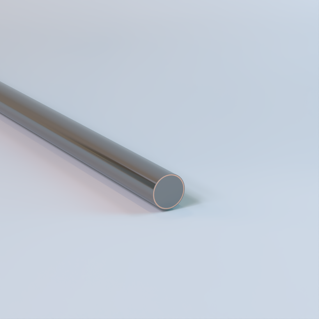
Copper-Clad Steel (CCS) Conductor with Camouflage Finish
Solid (Single End), Drawn Steel Alloy (DSA) Core, Metallurgically Bonded Copper Cladding, 39 AWG – 0 AWG, 40%, 30%, or 21% Conductivity, Hard-Drawn or Annealed, Low Carbon (LC), High Strength (HS), or Extra High Strength (EHS) Steel Core – Composite
Used for grounding and utility applications. Commonly specified for grounding elctrodes, counterpoise grounding systems, utility grounding and overhead static or shield wire applications where permitted by the National Electrical Code (NEC). Also available bare or with a PVC covering. Availability of conductivity class, temper, steel core strength, and finish varies by size and specification. Available from Copperweld®.
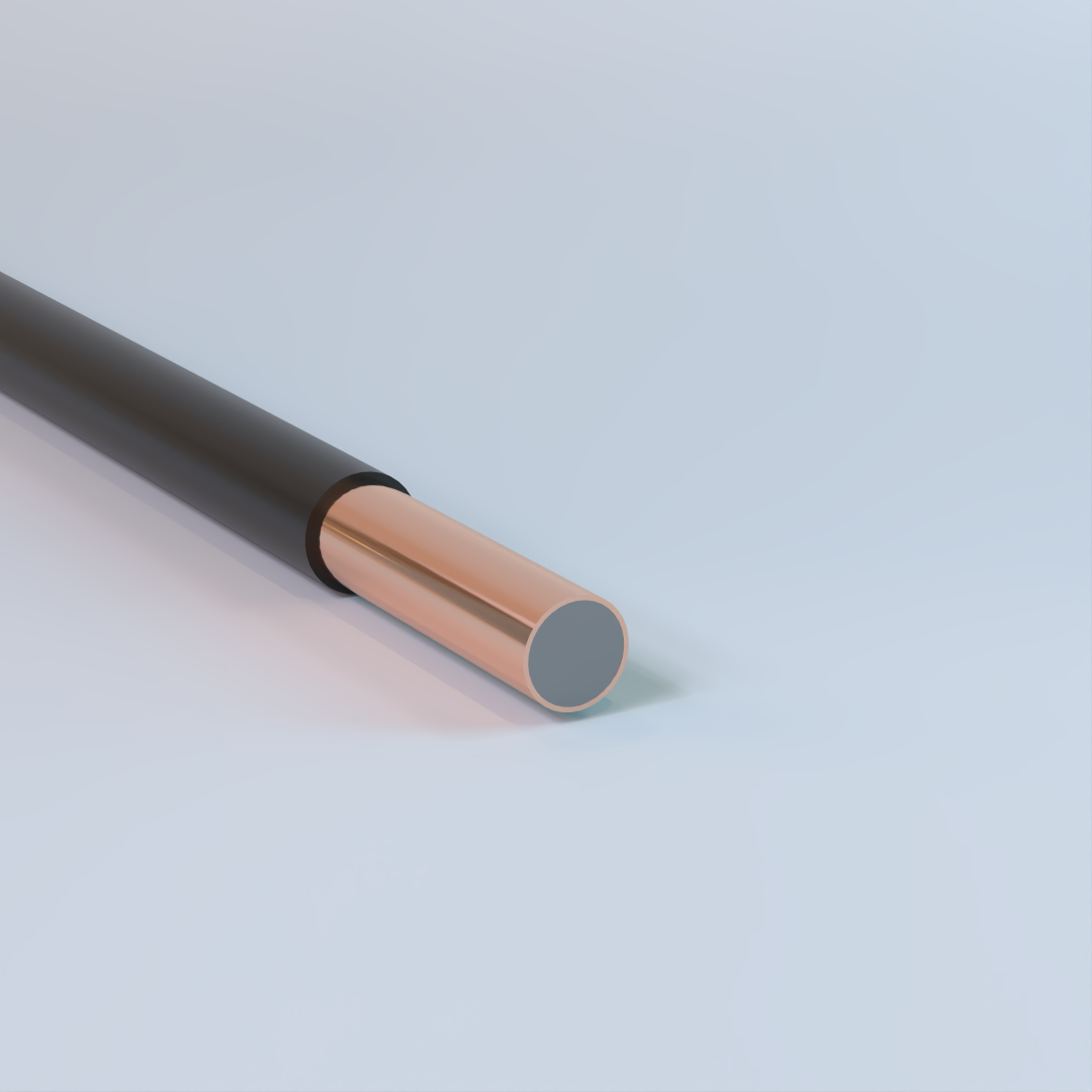
Copper-Clad Steel (CCS) Conductor with PVC Cover
Solid (Single End), Drawn Steel Alloy (DSA) Core, Metallurgically Bonded Copper Cladding, 39 AWG – 0 AWG, 40%, 30%, or 21% Conductivity, Hard-Drawn or Annealed, Low Carbon (LC), High Strength (HS), or Extra High Strength (EHS) Steel Core – Composite
Used for grounding and utility applications. Commonly specified for grounding elctrodes, counterpoise grounding systems, utility grounding and overhead static or shield wire applications where permitted by the National Electrical Code (NEC). Also available bare or with a camouflage (theft-deterrent) finish. Availability of conductivity class, temper, steel core strength, and finish varies by size and specification. Available from Copperweld®.
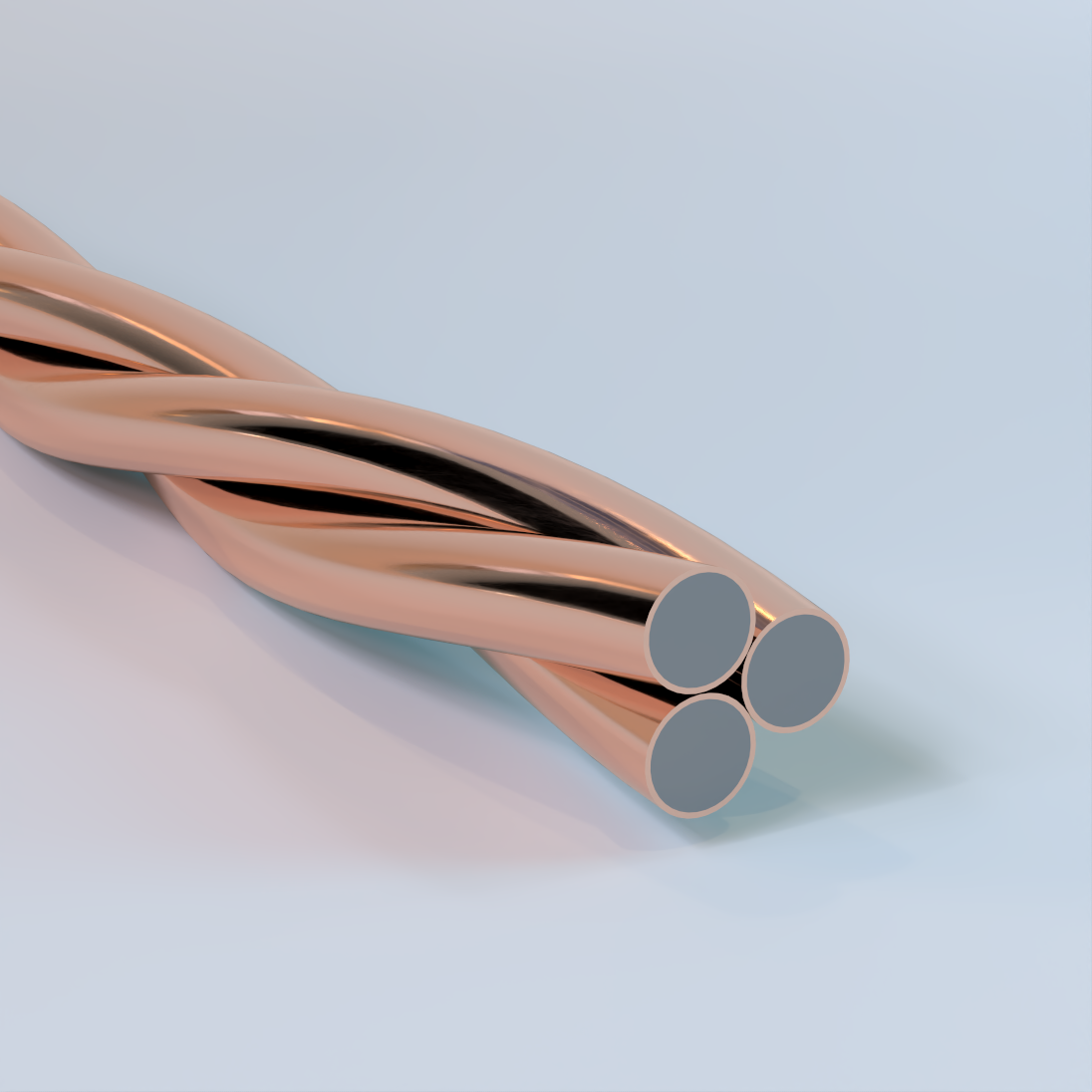
Bare Copper-Clad Steel (CCS) Conductor
Concentric Lay Stranded, Drawn Steel Alloy (DSA) Core, Metallurgically Bonded Copper Cladding, 3 Strand, 40% or 30% Conductivity, Annealed; Low Carbon (LC), High Strength (HS), or Extra High Strength (EHS) Steel Core – Composite
Used for grounding and utility applications. Commonly specified for grounding systems, counterpoise grounding, utility grounding, overhead static or shield wire applications, and associated bonding within grounding systems where permitted by the National Electrical Code (NEC). Also available with a camouflage (theft-deterrent) finish or PVC covering. Availability of strand construction, conductivity class, steel core strength, and finish varies by size and specification. Available from Copperweld® under the Century™ product line.

Copper-Clad Steel (CCS) Conductor with Camouflage Finish
Concentric Lay Stranded, Drawn Steel Alloy (DSA) Core, Metallurgically Bonded Copper Cladding, 7 Strand, Camouflage Finish, 40% or 30% Conductivity, Annealed; Low Carbon (LC), High Strength (HS), or Extra High Strength (EHS) Steel Core – Composite
Used for grounding and utility applications. Commonly specified for grounding systems, counterpoise grounding, utility grounding, overhead static or shield wire applications, and associated bonding within grounding systems where permitted by the National Electrical Code (NEC). Also available bare or with a PVC covering. Availability of strand construction, conductivity class, steel core strength, and finish varies by size and specification. Available from Copperweld® under the Century™ product line.
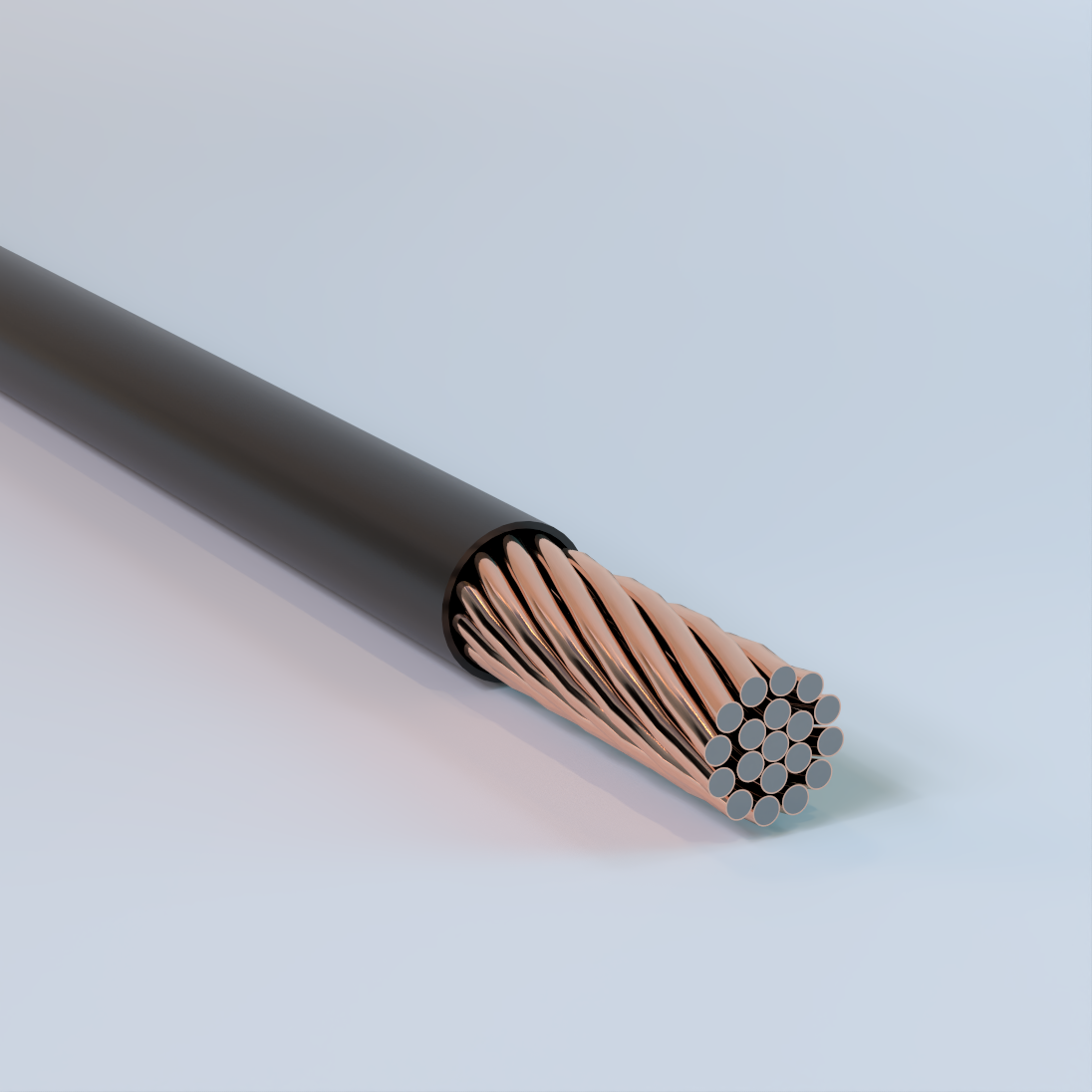
Copper-Clad Steel (CCS) Conductor with PVC Cover
Concentric Lay Stranded, Drawn Steel Alloy (DSA) Core, Metallurgically Bonded Copper Cladding, 19 Strand, PVC Cover, 40% or 30% Conductivity, Annealed; Low Carbon (LC), High Strength (HS), or Extra High Strength (EHS) Steel Core – Composite
Used for grounding and utility applications. Commonly specified for grounding systems, counterpoise grounding, utility grounding, overhead static or shield wire applications, and associated bonding within grounding systems where permitted by the National Electrical Code (NEC). Also available bare or with a camouflage (theft-deterrent) finish. Availability of strand construction, conductivity class, steel core strength, and finish varies by size and specification. Available from Copperweld® under the Century™ product line.
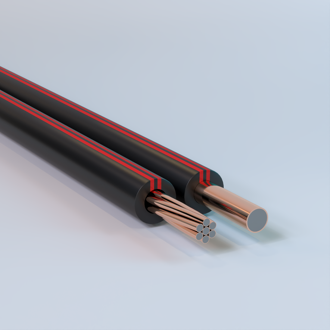
Copper-Clad Steel (CCS) Conductor High-Voltage Flexible Stinger Wire
Solid (Single End) or Concentric Lay Stranded, Grade 40 Drawn Steel Alloy (DSA) Core, Metallurgically Bonded Copper Cladding, 1 Solid or 7 Strand, Thermoplastic Elastomer (TPE) Insulation/Cover with UV Protection – Composite
Used as riser wire for cutouts and pole-top transformers, providing connections between primary phase conductors and equipment bushings, and for use as covered ground wire in distribution circuits. Available from Copperweld® under the Stingray™ product line.
Bare Copper-Clad Steel (CCS) Conductor
Concentric Lay Stranded, Grade 40 Drawn Steel Alloy (DSA) Core, Metallurgically Bonded Copper Cladding, 61 Strand & 19 Strand – Composite
Used for substation grounding applications where grounding conductors must carry short-duration, high-magnitude current during fault or arc events without thermal or mechanical failure. Commonly specified for substation ground grids designed in accordance with IEEE Std 80, which establishes conductor sizing based on the ability to withstand high fault current for a defined duration. The higher strand count provides increased flexibility and mechanical strength compared to solid copper conductors, supporting efficient installation and optimized ground grid design. Available from Copperweld® under the ArcAngel™ product line.
Bare Copper-Clad Steel (CCS) Conductor
Concentric Lay Stranded, Grade 40 Drawn Steel Alloy (DSA) Core, Metallurgically Bonded Copper Cladding, Tinned Finish, 19 Strand & 61 Strand including 1 Green Jacketed Indicator Strand – Composite
Used for substation grounding applications where grounding conductors must carry short-duration, high-magnitude current during fault or arc events without thermal or mechanical failure with an integrated indicator conductor for locating and identification. Commonly specified for substation ground grids designed in accordance with IEEE Std 80, which establishes conductor sizing based on the ability to withstand high fault current for a defined duration. The higher strand count provides increased flexibility and mechanical strength compared to solid copper conductors, supporting efficient installation and optimized ground grid design. Available from Copperweld® under the ArcAngel™ – Indicator product line.
Copper-Clad Aluminum (CCA) Conductor Photovoltaic (PV) Cable
Concentric Lay Stranded, AA 8000 Series Aluminum Core, Metallurgically Bonded Copper Cladding, Min. 10% Oxygen-Free Copper by Volume, XLPE Insulation, Direct Burial, 90° Wet or Dry, Sunlight Resistant, FV-1, Gasoline & Oil Resistant II, 2kV-Rated – Composite
Used as photovoltaic inter-panel, string, and homerun power conductors in solar power systems requiring voltage ratings up to 2,000V DC. Suitable for use in both grounded interconnection and ungrounded photovoltaic power systems, including PV source and output circuits exposed to outdoor environmental conditions Also available in red or white insulation/cover. Available from Copperweld® under the Sunray™ product line.
Bare Copper-Clad Aluminum (CCA) Conductor
Solid (Single End), AA 8000 Series Aluminum Core, Metallurgically Bonded Copper Cladding, 10% Oxygen-Free Copper by Volume, 38 AWG – 0 AWG – Composite
Used for grounding and utility applications. Commonly specified for grounding electrodes, counterpoise grounding systems, utility grounding and overhead static or shield wire applications where permitted by the National Electrical Code (NEC). Also may be available with a camoflauge (theft-deterrent) finish or PVC covering for select sizes.
Bare Copper-Clad Steel (CCS) Conductor Type M Guy Strands
Concentric Lay Stranded, Grade 40 Drawn Steel Alloy (DSA) Core, Metallurgically Bonded Copper Cladding, 7 Strand & 3 Strand – Composite
Used for guy wire (guy strand) and messenger wire (messenger strand) applications in utility, communications, and infrastructure installations where mechanical strength, corrosion resistance, and long service life are required. Suitable for applications requiring electrical continuity, bonding, or grounding compatibility where permitted by applicable codes and standards. Available from Copperweld®.
Bare Copper-Clad Steel (CCS)/Bare Copper (Cu) Composite Concentric Lay Stranded Conducters
Grade 40 Steel Core with Metallurgically Bonded Copper Cladding Conductor & Bare Copper Conductor – Composite
Used in overhead transmission and distribution systems where predictable electrical performance is required. These composite stranded conductors are applied in line and grounding configurations to evaluate resistance, inductive and capacitive reactance, geometric mean radius, and ampacity at 60 hertz. Commonly referenced for conductor selection, system modeling, and spacing analysis in utility and infrastructure applications. Available from Copperweld®.
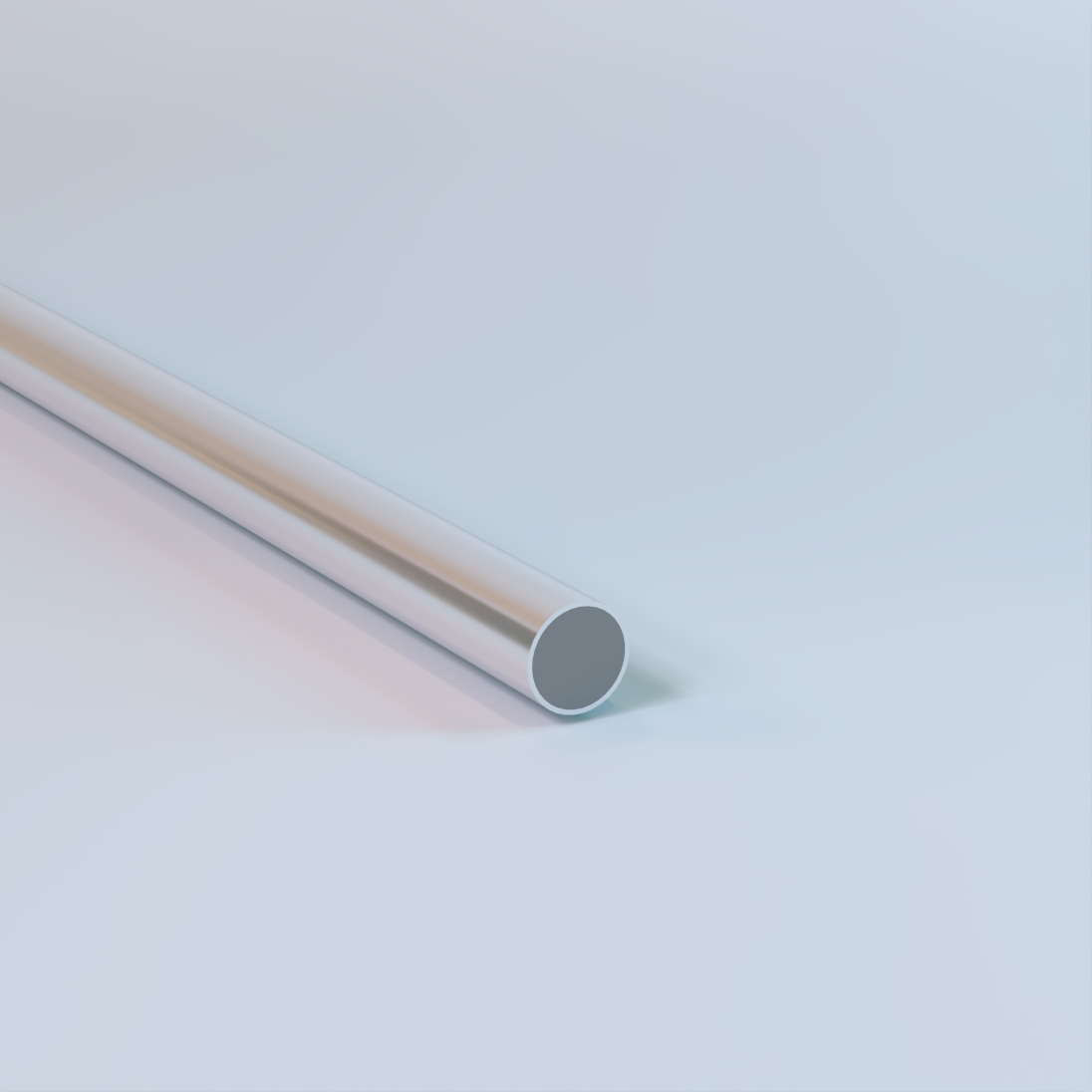
Bare Aluminum-Clad Steel (ACS) Conductor
Solid (Single End), Hard-Drawn Round Steel Core with Bonded Extruded Aluminum Cladding – Composite
Used for transmission and utility applications including overhead shield wire (static wire) and overhead ground wire installations. Provides lightning protection and grounding performance in transmission and distribution systems. Commonly specified for installations in high-corrosion environments including industrial, coastal, and desert regions. Also suitable for grounding systems, counterpoise applications, and formed wire applications such as dead-ends and related hardware assemblies. Availability of size, conductivity class, and mechanical strength varies by specification.
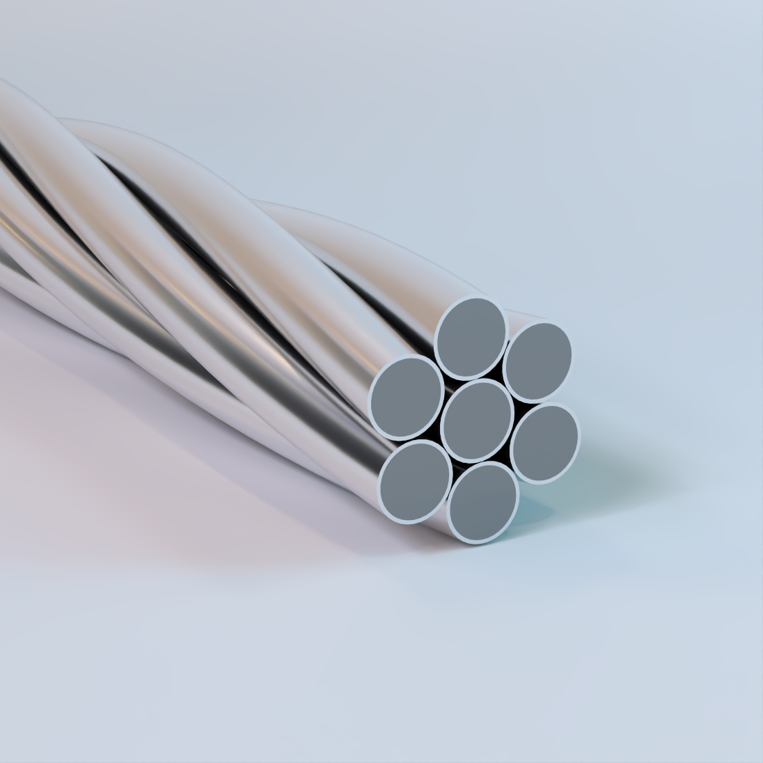
Aluminum-Clad Steel (ACS) Shield Wire
Bare Overhead Concentric Lay Stranded, Hard-Drawn Round Steel Core with Bonded Extruded Aluminum Cladding – Composite
Used for transmission and utility applications including overhead shield wire (static wire) and overhead ground wire installations. Provides lightning protection and distributed grounding critical to the safe operation of transmission and distribution systems. Commonly specified for use in high-corrosion environments including industrial, coastal, and desert regions. Availability of strand construction, size, and mechanical strength varies by specification.

Aluminum-Clad Steel (ACS) Guy & Messenger Wire
Bare Overhead Concentric Lay Stranded, Hard-Drawn Round Steel Core with Bonded Extruded Aluminum Cladding – Composite
Used for transmission and utility structural support applications including guy strand and messenger wire installations. Designed to provide high tensile strength and mechanical reinforcement for pole stabilization and aerial cable support systems. Commonly specified for use in high-corrosion environments including industrial, coastal, and desert regions. Availability of strand construction, size, and mechanical strength varies by specification.
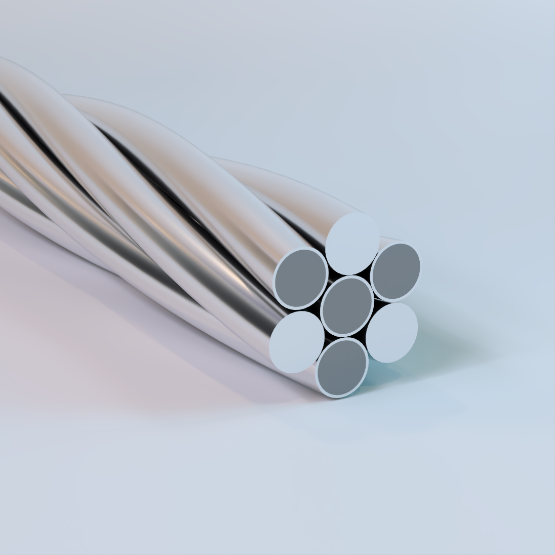
AWAC (AS/AC)
Aluminum Conductor, Aluminum-Clad Steel Reinforced, Bare Overhead Concentric Lay Stranded Conductors – Composite
Used for transmission and utility applications including overhead phase conductors where increased span length and mechanical strength are required. Commonly specified to improve conductor clearances and structural performance in transmission and distribution systems. Also utilized as neutral messengers for spacer cable systems and in certain ground or shield wire and self-supporting cable applications. Availability of strand construction, size, and mechanical strength varies by specification.
Utility Steel Strand
Guy, Static & Messenger Wire, Galvanized or Zinc-5% Aluminum Alloy Coated, 3 Strand, 7 Strand & 19 Strand – Steel
Commonly referred to as galvanized guy wire, it’s used for structural support and stabilization in electric utility and communications infrastructure including, pole guying, overhead static and ground wire applications, and messenger cable support. It provides high tensile strength and long-term corrosion resistance in outdoor environments. Galvanized (zinc-coated) strand is for reliable performance in standard utility installations, while zinc-5% aluminum alloy coated strand offers enhanced corrosion protection for coastal, industrial, and extended design-life applications. Designed to anchor and stabilize poles and towers, support aerial cable systems, and provide dependable grounding continuity where uninterrupted mechanical and electrical performance is required. Stocked primarily in extra high strength (EHS) grade. Other grades available upon request.